• Please review our updated Terms and Rules here

PS/1 2011 ACU project

Howdy folks. Nice work on these ACU card designs! @whaka and @Theoryboy, I'm glad you're working on this.

Do you think you will release either of your designs as Open Source, maybe even just publish your EDA or PCB design files? Or do you expect you'll just treat this as a commercial project?

I'm tinkering around with my IBM PS/1 model 2011, and I am interested in trying to make my own breakout/dev board for the ACU slot -- I gather it uses the same mechanical specs as a PCI slot, but I note that it has 112 pins (I think; 56 x 2) instead of PCI's 120 pins (or whatever it is). Do you have any specs for this that you can share?

In any case, keep up the good work! Cheers :)
 
I gather it uses the same mechanical specs as a PCI slot, but I note that it has 112 pins (I think; 56 x 2) instead of PCI's 120 pins (or whatever it is). Do you have any specs for this that you can share?
as MCA slot :) it's actually the same connector as 16 bit MCA, but used for ISA.
for technical documentation, you can go on the hottobar site, a nice guy who shared the technical reference book for our machines : https://ps1stuff.wordpress.com/download/downloads-for-type-2011/

i think i'll open my project at some point, but for the moment, i keep it "for me" :D
it's in stand-by, but i have to rework a bit the self powered adaptor. i've made a wrong choice with a fixed 5V regulator.
need an adjustable one to raise the voltage when no load (like any psu does...) to keep in safe margins when loaded.
 
Ah cool, thanks whaka. Yeah, hottobar’s ps1stuff site is great :)

I’ve designed a rough prototype riser similar to Theoryboy’s, and I’m waiting for the PCBs to arrive from JLC.

it's in stand-by, but i have to rework a bit the self powered adaptor. i've made a wrong choice with a fixed 5V regulator.
need an adjustable one to raise the voltage when no load (like any psu does...) to keep in safe margins when loaded.

I’m not experienced enough yet with different PSU designs, and I would like to know more about what you mean about replacing the fixed 5V regulator. I understand the LM2596 is a buck switching regulator… what alternative would be better? I notice your recent photo shows a custom power converter board plugged into the PS/1 2011 motherboard, right...?

I saw the doco says the ACU could supply 4.2A typically. My prototype, without its own PSU, ignores the +36V for now. I’ll test with just 1 card running off the ACU slot’s own +5V line. I wonder how much current it can deliver? Theoryboy mentioned drawing 200mA OK. Hmm… I wonder if this 5V line is for the ACU’s power card “+5REF” line?

Anyway, I'm finding this an entertaining project. I hope you manage to post updates or other photos in a while :)
 
I understand the LM2596 is a buck switching regulator… what alternative would be better? I notice your recent photo shows a custom power converter board plugged into the PS/1 2011 motherboard, right...?:)
the LM2596 also exist with adjustable output, so i just have to manage some place to put a variable resistor somewhere.
and yes, you saw right, i also made a pico psu adaptor, with the possibilty to power the ACU. it's a far better way, but if you care about machine integrity... :D

and another yes, it's the +5REF, and not safe to draw power. the copper track is thin, and may burn easily.
 
I will follow this project with a lot of interest! The IBM PS/1 2011 is a great little machine indeed :)

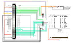
In the meantime, for those of you who'd like to add sound, you can do so quite easily by crafting a simple passive adapter to connect the Audio Card connector to an 8-bit ISA port. This supports OPL2 FM only since some lines are missing for digital sound.
Here's a video I did on that subject:
 
it's the latest available from last month.
the bios need to be patched for using version 2 of the xtide rom.
for the moment, this can be considered as a kind of kludge, as you can't boot the original hdd without the xtide.
there's certainly a way for making a dedicated xtide rom for the ps/1, but it's far beyond my knowledge.
Which one needs patching? The system BIOS or the XUB?
 
I find it very interesting, I did something similar just to address the lack of sound on the thing , things also didn't work as I expected them to.
XTIDE etc. It will be interesting to see what you can get working in the thing.


View attachment 1040501
Great project, I'd love to build one for my 2011. Would you mind sharing the gerbers?
Cheers
 
Hello, this is great project from @whaka!


I'm also interessed, for some time, on making a ACU for the 2121 model that uses the same 2011 main unit case (the low profile one).

@retrotomat also shares a great way (and simple aproach) for using 8-bit ISA cards!


I'm glad that you all share your findings and precious information
:)
 
Hello @retrotomat
I've used you approach to install successfully an AdLib clone OPL2 card on a PS/1 model 2121 without ACU!
But unfortunately as soon I tested it I notice that the sound was low pitched...
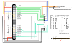
I was previously aware (from Vogons - IBM PS/1 Audio Card thread) that this connector for the "PS/1 Audio Card" uses a different clock signal frequency of 10MHz instead of 14.31818Mhz like a standard ISA, so I had to adapt the schematics based you shown in your previous youtube video:

PS1isa8bitConv14Mhz.png

in order to get the correct ISA clock frequency, which is present on pin A37 of proprietary 2121's ACU connector (physically identical to an "MCA 16 AVE connector")
Now the Adlib Card sounds correctly pitched. :)

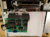
Here is the final instalation of the card:

photo_2023-09-22_23-24-27.jpg
 
Last edited:
Interesting! I'm glad you made it work on your 2121 :)

I missed out the fact that the audio connector CLK signal wasn't the same as standard ISA.
Most of the OPL2 clones I've tried (Texelec Resound OPL3, Snark Barker, SB16) sound fine with the 10 MHz CLK but I had issue with some others (Adlib replica, Aztech with OPL3) so that may explain why. I'll try again with your mod to see if that fixes it.

BTW, on the modified schematic. the new red wire goes from the ACU to the audio connector CLK pin. Shouldn't it connect the ACU connector to the ISA slot on pin 30 (OSC) instead?
 
Last edited:
Hi @retrotomat, you are absolutely right!
I was going through the image edition over the 4th pin of the "ps1 audio connector" and forget to validate the isa B30 pin...
Thank you for pointing that!

The correct schematics are:
PS1isa8bitConv14Mhz_2.png
 
Back
Top