• Please review our updated Terms and Rules here

PS/2 Edge connector to 34 pin resistors?

Maikudou

Experienced Member
Joined
Aug 20, 2023
Messages
238
Location
SF Bay Area
I have 3 PS/2 FDDs, all different, 2 were working after cleaning and recapping, the 3rd one by Alps resisted my attempts and refused to work (there is a lot of oxidation on SMDs, it played completely dead). Luckily it had a separate small PCB with edge connector which connected to the drive via a thin ribbon cable, so it can be used as an organ donor. I have masterfully butchered soldered a 34pin + berg connector to use with one of my Nec drives and it works perfectly:
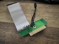
IMG_3687.jpg

But here comes the question, I have noticed, TexElec's and ZZXIO's ones both have resistors, TexElec's even 3 different packs. Why? Does PS/2 sends too much current, or on the contrary, garden variety drives do that to poor unexpecting IBM? Why does one might need resistors on something which at least according to https://www.ardent-tool.com/floppy/Pinouts.html and https://en.wikipedia.org/wiki/Floppy_disk_drive_interface should be a simple passive interface switcher?

A separate question, more l like a curiosity, as it provides 12v too, can I use 5.25 drive, or will it be blasphemy?
 
Last edited:
Of course I've read on Tex Elec website that "it did not work in some combinations" but why might it be not working? Too long ribbon cable? Too much interference? Different electrical parameters expected? "You did not use Part Number prescribed in IBM PS/2 Technical Reference Manual and must suffer"?
 
The resistors you speak of are probably terminating resistors to prevent signal reflections bouncing back and forth along the signal cables between the drive and the PC motherboard.

On a multi-drive system, it would be the last drive in the chain that contained the terminating resistors.

Without any further details, that would be my best guess.

There are a few different systems that can use the drives. Sometimes the drive can be configured for most of them but, just occasionally, they can't.

Welcome to the world of Standards (or not)...

Older floppy drives tended to use +12V for the motor and +5V for the logic.

More modern floppy drives (especially 3 1/2") tend to use just +5V for both duties. They do not, therefore, require the +12V supply. However, the current consumption of the +5V supply has increased as a result...

You can't get something for nothing!

Dave
 
Termitaion was the first that came to mind. But should not it be an issue for a generic FDD in a generic PC too? One does not set up termination on 3.5 FDD if I remember correctly, it is almost always the last drive (after the twist), so are they expected to have termination on by default? Pulled a couple of 3.5 drives, can't see any user-accessible jumpers for termination on either.
 
If termination is ON by default, and you have two floppy drives (one before the twist and one after) then that means you have two lots of termination resistors acting.

I will have to check some of my drives to answer that.

Dave
 
Some pins on PS/2 FDDs also use pins to sense the drive type. Could be that these resistors might simulate the signals absent from commodity Shugart-type FDDs.
 
Hm, there are additional pins on PS/2 34 pin connector implementation, but not on edge connector one, according to https://www.ardent-tool.com/docs/pdf/ps2_fdd_trm_s42g2194_00.pdf

It is plausible to me that on generic 90s PC no one used two 3.5 inch drives and they are all terminated by default. 5.25s I have on the other hand have a lot of jumpers. It might explain why I could not make this work when I tried to use this 3.5 before the twist with 5.25 after the twist, even if both was correclty set to be drives B. It is unrelated to PS/2 though, it was on a ATX Dell machine, still interesting to know such caveats..
 
So I have just looked at my Teac FD-235HF drive and it has non-removable 1 kOhm pull-up resistors.

All of the 5 1/4" drives I have contain removable resistor packs.

There ARE some links though, related to various drive options (e.g. which signal Drive READY and disk change appear on (or whether the signals are used or not).

Dave
 
Makes sense, what is what I was expecting in regards to 5.25. I will check later my proper PS/2 3.5 drives for terminators out of curiosity: "Flat" PS/2 models clearly have room for two 3.5 FDDs, so there should be way to either disable the terminators on one, or maybe it just uses it differently, like two "channels" not one after another. My PS/2s do have riser card, not ribbon, will trace how the second connector is wired on it.
 
Back
Top