• Please review our updated Terms and Rules here

QBus SRAM card thoughts...

bladamson

Veteran Member
Joined
Nov 11, 2018
Messages
986
Location
Appalachia
So I have been looking over this: https://www.5volts.ch/pages/qbusmemory/qbusmemory/

It's a 4 meg sram card for qbus using modern-ish components. I want to use this (the cpld code in particular) as a path to building my own on a glitchworks protoboard, except with 512k x 8 through hole srams instead of the surface mount stuff he's using. I don't think that will be a huge issue, just a matter of some extra chip select decoding. However it says on the web page.......

"The current CPLD design only supports normal DATI and DATO/DATOB cycles. However the circuit has been made with block mode DMA in mind and all necessary signals connect to the CPLD and connect with the Q-Bus if required."

I am pretty green on PDP-11 stuff, so what implications does this have as far as what operating systems will work with the card? Is this going to cause any trouble with RSX-11 or 2.11BSD? I have a vintage 32kW card that appears to work that I can use for RT-11 if I have to, and I have a qbone to assemble that can emulate memory if the lack of DMA support in the above CPLD design will prevent me from running RSX-11 or 2.11BSD on it. But ultimately I'd like to emulate as little as I can realistically get away with.

Thanks folks. I apologize for my ignorance and I really appreciate any advice you have.
 
keeping an eye on this as well, very interested in following your footsteps- as much as i love the qbone, there's just something nice about having actual physical memory.
 
QBUS block mode transfer is just a low level performance optimization. If DMA devices are going to do successive transfers they can request to do it via block mode and utilize the QBUS more efficiently and achieve better DMA transfer performance. If the memory does not support block mode it reverts to multiple individual transfers. Should have absolutely no affect on software running on the CPU.
 
As Don said it is the device that requests block mode DMA (using some handshaking involving the BBS7 signal) and if the Memory does not respond to the block mode request (i.e. does not assert BREF) then the device assumes the memory is not block mode DMA and will perform a simple DATI/DATO.

The logic without block mode DMA support is very simple. The ATF1504 are available in a PLCC-44 package with through hole sockets available but they won't fit on a test board with DIP in mind. That said it most likely is very easy to implement the logic using discrete TTL. If you are going to use byte-wide SRAM then you need individual WEL and WEH signals that replace LB, UB and WE. Also with discrete TTL you could use some RC delays instead of the binary delay line solution.
 
The logic without block mode DMA support is very simple. The ATF1504 are available in a PLCC-44 package with through hole sockets available but they won't fit on a test board with DIP in mind. That said it most likely is very easy to implement the logic using discrete TTL. If you are going to use byte-wide SRAM then you need individual WEL and WEH signals that replace LB, UB and WE. Also with discrete TTL you could use some RC delays instead of the binary delay line solution.

An in-between solution is you could probably split the ATF1504's logic up over several GALs if you really wanted a DIP-friendly solution across the board but still wanted to save some logic compared to discrete TTL.
 
I have plenty of through hole plcc-44 sockets, but the only ATF15xx I have on hand are the 1502, which may not be complex enough, I dunno. We shall see!!

If soldering kynar wires to the PLCC44 socket proves too difficult, ebay is full of el-cheapo plcc44 to dip adapters. I think I may have a couple somewhere that I was using for breadboarding.

I do like the idea of doing it more discreetly though, but I shall have to study up better on the qbus timing and latching and all that. Maxim makes some cute little 8 pin multiple delay line chips that would probably be able to get the timing where it needs to be maybe; i dunno.
 
My brain is reduced to pudding after a rough afternoon of debugging build scripts (aaaagh!), but it my ignorant take on the ATF code is it looks like it does a delay line simply by taking the source crystal's tick (the value of which apparently isn't very critical) and dividing it by walking each tick through some latch registers. (Understanding other people's CUPL code is, well, a yet-to-be-much-developed skill, but unless there's something I don't know it doesn't even look like it's exactly a counter/reset situation, it's just a chain?) I would need to read and at least noddingly understand the qbus docs to understand why it's there. Something a pudding brain's not up to.
 
I assume that the delay line has something to do with the bus latching, but I haven't read up on it yet. Long day. D:
 
If GALs are an option, then I would go for the GAL solution to replace the ATF1502. And yes the delay line is just a chain.
 
If it helps at all I have galasm .PLD code to do various clock divides from 1.5x and up with a GAL. (Obviously the duty cycles aren’t always 50/50…)
 
Actually you just can use WinCUPL and distribute the equations of the CPLD to 2 or 3 GALs

In fact the logic is very simple. E.g. RDIN0, 1, 2 and RDOUT0, 1, 2 can be generated by a single 74LS174, the signals latched within the CPLD can be latched by an additional 74LS573 and the rest of the logic fits in a single GAL22V10. This GAL then generates XMIT REC CE OE WEL WEH TRPLY LE. In fact a GAL16V8 would suffice, but with the larger one you can generate more CE for additional SRAM. Or you could drop in a 74LS139 to select up to 4 RAM rows to create a 4Mb using 512k SRAM.
 
Last edited:
@cbscpe , this thread is quite timely for me, as I just finished building a copy of your qbus 4mb sram board. I'm struggling to program the atf1504, though, as I don't have the Atmel/Microchip USB programmer, just a FlashcatUSB JTAG programmer, so I can't figure out how to convert the .jed file that I generated with WinCUPL to an SVF that FlashcatUSB can program.

Do you have the ability to share an SVF, or have any suggestions on programming the board? I could, of course, buy the Atmel programmer, but it is _very_ expensive for a one-time-use device.

- Alex
 
I program my 1502s with a cheap USB blaster, but I have never tried to program a 1504. I haven't tried to build that guy's circuit, and afaik he's not on these fora to ask about it. I'll probably use a GAL and maybe a Maxim delay line if needed for the bus timing, rather than a CPLD (which seems maybe a little overkill for what it needs to do, but maybe that's just what the guy had on hand).
 
Do you have the ability to share an SVF, or have any suggestions on programming the board? I could, of course, buy the Atmel programmer, but it is _very_ expensive for a one-time-use device.

- Alex

I don't have any experience using these tools myself to verify that this all works. This Atmel doc says that the Atmel-ISP software can be used to generate a Serial Vector Format (SVF) file.

https://ww1.microchip.com/downloads/en/Appnotes/DOC1613.PDF
Creating Atmel JAM/JBC File(s) for the ATF1500AS Device Family

https://web.archive.org/web/20150926233827/http://www.atmel.com/tools/ATMISP.aspx
https://web.archive.org/web/20160217090611/http://www.atmel.com/images/ATMISP67.zip
https://web.archive.org/web/20160217090615/http://www.atmel.com/images/ATMISP7.zip
 
Yeah, I tried that, but atmisp only works when it’s attached to the device with the atdh1150usb cable. Otherwise, all the actions are greyed out.

- Alex
 
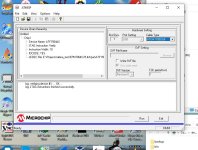
So I have a little test board with an ATF1504AS PLCC44 in it attached to an ATDH1150USB pod and ATMISPv7.3 on my system.
So if you can send me a file I can see if I can convert it for you.
Normally I don't use CUPL or any of the Atmel tools except for POF2JED to convert Altera EPM7K series parts from Altera .POF to Atmel .JED files.
I do the device image generation in verilog using Quartus 13.0sp1.
Capture.JPG
 
Yeah, I tried that, but atmisp only works when it’s attached to the device with the atdh1150usb cable. Otherwise, all the actions are greyed out.

- Alex

Which version of Atmel-ISP did you try?

The description for version ATMISP v7.2 says "This version of ATMISP supports the ATDH1150USB USB based ISP cable only and is supported on Windows 7 and 8 operating systems."

The description for version ATMISP v6.7 says "This version of ATMISP supports the ATDH1150PC/VPC and compatible LPT port based ISP cables as well as the ATDH1150USB USB based ISP cable, and is supported on Windows 2000 and XP operating systems."

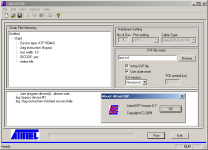
I tried version 6.7, which let me create an SVF file without any programming hardware attached.

Atmel-ISP-67.png
 
Hmmm v6.7 might work without hardware present because it can't really detect that the LPT based dongle is attached (or not).
The USB-only later versions like v7.3 that only support the USB dongle can detect if it is there, or not.
 
Back
Top