onesimus
Experienced Member
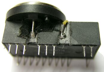
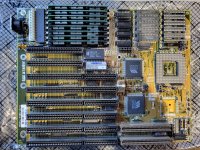
Hello all! I recently bought an FIC 4386-VC-V motherboard from ebay. Unfortunately though, it has one of the Dallas clock chips. Now, I've seen the replacements for these, whether they be the Necroware stuff or just a new Dallas chip. However, on the back of my motherboard, near to the clock chip, someone has soldered a resistor. I've looked high and low online to try to see if this is some sort of known way to bypass the chip or something like that, but all I've seen people talking about is taking the chip out and replacing it. You see, I'm not so great with electronics like this, so I know what a resistor does, but I don't know what it's doing here. Was really hoping someone here is into electronics like that and be able to provide some info.
I just have a couple of questions:
Has anyone seen anything like this before?
What could this be for and how does this work?
Has anyone messed with this particular board and know whether or not it will POST with a dead Dallas chip? (a long shot I know)
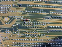
Also, some have looked at the photos and said that the resistor is not attatched to the clock chip, but if you look closely, one of the traces that the resistor is connected to does actually does go to it, but goes somewhere else as well. Check out the top row on the dallas chip, 4th pin from the left, following the trace. You'll see it goes to the resistor.
Thanks and may the light of Christ shine in each of your lives!
I just have a couple of questions:
Has anyone seen anything like this before?
What could this be for and how does this work?
Has anyone messed with this particular board and know whether or not it will POST with a dead Dallas chip? (a long shot I know)
Also, some have looked at the photos and said that the resistor is not attatched to the clock chip, but if you look closely, one of the traces that the resistor is connected to does actually does go to it, but goes somewhere else as well. Check out the top row on the dallas chip, 4th pin from the left, following the trace. You'll see it goes to the resistor.
Thanks and may the light of Christ shine in each of your lives!
Attachments
Last edited: