• Please review our updated Terms and Rules here

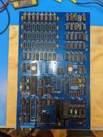
Recreating the Ferguson Big Board

Started building one up but quickly realized I let my stash of 14 and 16 pin dip sockets has run low. :( So will be a few more days for those to come in.

Did spend a bit of time designing a couple lead forming tools to take those cheap MLCC caps with 5.08mm lead spacing you find on Aliexpress to the 6.35mm needed by this board. So I can now spend my time bending 100+ caps while I wait for more parts in the mail.
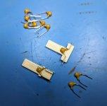
PXL_20230820_202353289.jpg

Also picked up some large padded mailers so if anyone in the US does want to jump in at this point and try to bring one one of these up with me, shoot me a DM and I can drop one of the extra boards in the mail for $20 shipped.
 

Attachments

  • 6.35mm Lead Bender v2.zip
    59.4 KB · Views: 12
Got everything soldered in and started uploading docs to Github. Found two unconnected traces so far, documented at https://github.com/djtersteegc/Ferguson-Big-Board-Reproduction. Ignore the bodge on U75, that 74LS151 had a broken pin so it's a temp fix until new chips come in.

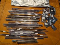
PXL_20230827_181326132.jpg

My UTSource order is going really, really slow this time so I scavenged all the old corroded IC's off the built board I had (untested, long story) and started cleaning them up. All the logic and RAM tested good (yay!), but I'm still missing a few chips since the other board had a Double Density disk mod, and was setup with a 74LS86 in U94 for split video, and I need (and don't have currently) a 74LS136 for composite video.

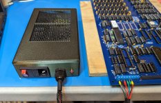
So, my next plan today is to try to get serial outputs working today and use a terminal instead or the video/keyboard while I wait for chips. Wish me luck screwing up TX/RX wiring order at least once while building the cable.
 
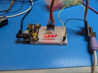
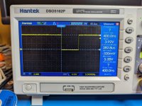
Switched gears a little bit tonight and decided to test the PS/2 to parallel keyboard adapter just to make sure it's working as expected. Fortunately it does. Was also able to confirm the strobe pulse is active low, with a 280us duration, in this design so JB6 on the Big Board should be strapped for negative strobe, center to the right pin.

PXL_20230829_040246645.jpg
PXL_20230829_021951228.jpg
 
Last edited:
Finished installing sockets, headers, transistors and bypass caps last night. Starting on the other caps and resistors.

Waiting for a (hopefully Friday) delivery from Digikey for a few misc. parts. It's a beautiful board, I feel like I'm back in 1981!

- Gary
 
On the board troubleshooting front, the IORQ line never goes low (active) and instead just hovers around 3.4V. Swapped around the 74LS241 (U82) that buffers that line and tried a different Z80 chip with the same results. Basically it's never trying to select/enable chips like the PIO or SIO to poll them for input. Address and data lines have activity, and other lines like RD, WR, MREQ, and M1 look OK (I think), so at this point it's probably time to break out the logic analyzer and see what instructions are actually being fetched and executed from the PFM EPROM (U67).
 
The IORQ line seems to have continuity to/thru the buffer and out to the PIO's/SIO/CTC and 74LS138 (U85) and the individual chip select lines seem to be correct.

The Chip select lines to Baud "A" and Baud "B" are reversed on the schematic, and the KBD/Floppy PIO's IORQ pin is incorrectly labeled as 34 (it's 36).

- Gary
 
Woohoo, substantial progress at last. Found another missing connection on U81 that was preventing CE from being asserted on the PFM ROM. After patching, INT and IORQ are now being asserted on repeated keypresses, so ROM code appears to be running on the Z80. Still no monitor output, but that will be tomorrow's goal.
 
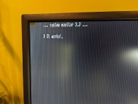
Huge step forward! PFM came up on the serial port!!

I'm having dram errors on banks 0 (0-3FFF) and 2 (8000--BFFF) but banks 1 and 3 test fine. Could certainly be my DRAM (or soldering) as the 4116's have been in tinfoil since about 1983.
 
Nice Gary, I'm still stuck at the SIO. See the bytes coming in, see the CE line behavior change when I hit a key to initialize the monitor, but no SIO output (yet).

I also confirmed it stops polling the SIO when you hit a key on the keyboard after reset so it also feels like the keyboard init is working, but I wasn't able to get composite output last night and wasn't seeing any activity on the CE or OE lines on the video ROM last night so something trace wise could also be missing there still.
 
Not to point out the obvious, but make sure it is an SIO/O or DART. SIO/1 or SIO/2 won't work (without some fudging). Also make sure you don't have an 8116-5 or 8116-6 as they have different dividers. All lessons I learned the hard way when I was building up BB1's for folks in the 1980's!
 
Yep, tried the original unreadable chip which I'm assuming was an SIO/0, a Z80 DART I picked up from Jameco, and a MK3884 that just showed from UTSource. All exhibit the same behavior. Definitely reading the first SIO byte since the keyboard poll is disabled, but never asserting BAUDB (yes, the schematic is reversed on sheet 1, should be pin 17 on U85) to set the COM8116. Must be stuck in the autobaud loop in PFM. Anyways, lots of new (old) chips now so I may try a few more swaps to see what happens.

PXL_20230902_171829531.jpg
 
OK, the BAUDB is being asserted (the schematic issue is on sheet 5, BAUDB goes into pin 12 on the 8116, BAUDA is pin 8). But no output on pin 17 of the 8116, could be a bad chip, or bad crystal. Have extra crystals, but no extra chips right now since this was missing on the original BOM in the manual so I didn't get them on my first order. :(
 
Composite output has been achieved! Two more unconnected pins in the video logic area of the board. In both cases they were long east west traces on the top copper that instead of jogging up to bisect the pin, had a tiny north south stub that connected to the pad. Ughhh

Not the prettiest signal currently and occasionally the scrolling jumps back up the screen, so still some more poking to do. Also, both JB7 and JB8, the two new video related jumpers I added need to be strapped between the top two pins to get any output, so need to do a little more reading to figure out what is going on there also. There were so many "improve your video" articles/letters in Micro Cornucopia it seems like this was a big area of modifications back in the day.

Since I have some output though, going to tackle the disk interface next since I now have FD1771 chips and see what kind of horrors I discover there.

PXL_20230902_210115035.jpg
 
I believe the line "U37 pin 6 should be connected to trace running immediately below it to connect to U38 pin 10 and U10 pin 9" should really be U10 pin 5?
 
I believe the line "U37 pin 6 should be connected to trace running immediately below it to connect to U38 pin 10 and U10 pin 9" should really be U10 pin 5?

Yep, nice catch. Also, thanks for the 8116 offer but I managed to pillage one temporarily from a Kaypro (an AY-5-8116) to get my serial also working. It was indeed a bad chip.
 
Back
Top