Upcoming Events:
- VCF South West - June 14 - 16, Davidson-Gundy Alumni Center at University of Texas at Dallas
- VCF West - Aug 2 - 3, Computer History Museum, Mountain View, CA
- VCF Midwest - Sept 7 - 8 2024, Schaumburg, IL
- VCF SoCal - Mid February 2025, Location TBD, Southern CA
- VCF East - April 2025, Infoage Museum, Wall NJ
-
Please review our updated Terms and Rules here
You are using an out of date browser. It may not display this or other websites correctly.
You should upgrade or use an alternative browser.
You should upgrade or use an alternative browser.
Recreating the Ferguson Big Board
- Thread starter hideehoo
- Start date
gekaufman
Experienced Member
I converted the standard Big Board BB1 through BB4 IMD files to IMG format and then created a custom Flashfloppy format definition for them in IMG.CFG. All the files are at https://github.com/djtersteegc/Ferguson-Big-Board-Reproduction/tree/main/flashfloppy, just copy them to a USB stick and stick it in your FlashFloppy. I also just added a GAMES.img disk that my son created last weekend by transferring via PIP of some of the classic CP/M games.
The original BB1 looks great as well! Should be a fantastic display.
How did you convert the .imd to .img files?
Still working on the floppy interface. I didn't think it thru well and tried to use an adapter I had previously designed to hook an 8" drive to a "modern" 5.25" interface. Unfortunately it doesn't work well in the other direction.
hideehoo
Experienced Member
The original BB1 looks great as well! Should be a fantastic display.
How did you convert the .imd to .img files?
Still working on the floppy interface. I didn't think it thru well and tried to use an adapter I had previously designed to hook an 8" drive to a "modern" 5.25" interface. Unfortunately it doesn't work well in the other direction.
The software package for HxC Floppy Emulator, https://hxc2001.com/download/floppy_drive_emulator/
Load the IMD and then export as IMG. Should be exactly 256,256 bytes when correctly exported.
Less than $5 to get five PCB's of https://github.com/pski/fd50to34 shipped to your door in the US from JLCPCB. Couple more bucks for IDC50 and IDC34 connectors (naturally I use the cheap ones from AliExpress). Works great, don't even have to set/solder any of the jumpers in this use case.
gekaufman
Experienced Member
Thanks for the conversion info.
I actually saw the same fd50to34 PC board and ordered it earlier today.
I had made up a similar board years ago. I tried it tonight - had to move the "Ready" pin 34 on the 5" side to pin 22 on the 8" side and it booted. It was great to see CP/M again!
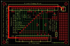
Happy to share the design and gerber files if anyone would like them. The test points can be handy.
Lastly, a 74LS145 works fine for the 7445. I suspect a 74LS42 would also work although I haven't tried it yet.
- Gary
I actually saw the same fd50to34 PC board and ordered it earlier today.
I had made up a similar board years ago. I tried it tonight - had to move the "Ready" pin 34 on the 5" side to pin 22 on the 8" side and it booted. It was great to see CP/M again!

Happy to share the design and gerber files if anyone would like them. The test points can be handy.
Lastly, a 74LS145 works fine for the 7445. I suspect a 74LS42 would also work although I haven't tried it yet.
- Gary
enrico
Experienced Member
Hi everyone, great work.
A few years ago I gave up because I was busy with my job with a small Bed & Breakfast here in Pisa, Italy.
During his time I gathered as much information as possible.
I was in contact with Richard Erlacher from Denver.
And i started scanning many microcornucopia numbers that I still have here.
In Italy in 1981 a small company managed to import and clone the original board that I still have and from which I began to rediscover the history
(I even managed to find the SWP card and used a xerox disk. In fact it works on both the xerox 820-1 and Bigboard1 simply by inserting it into the 1711 socket)
subsequently the same company added 256KB memory and 4MHz clock practically integrating what was made available on the microcornucopia manufacturer
ne ho anche uan versione successiva
A machine was therefore created to read how many formats of different floppy disks to import them running on IBM370 at the CNUCE (CNR) in Pisa
I have all the boards, firmware and software and I am available for any support on this fantastic project.
I also have a Ferguson Bigboard II and related software
Let me know if you need anything.
I sit with you with passion.
enrico@vintagesbc.it
hideehoo
Experienced Member
hideehoo
Experienced Member
hideehoo
Experienced Member
Thanks to everyone who picked up a v1.0 board on VCFMW, hope your build goes well. Now it's time to plan for v1.1. Here's my initial thought on changes...
1. Fix all the v1.0 errata (missing traces), including the factory bodge needed on U73 (the video ROM).
2. I had a hard time getting a Goldstar branded 74LS123 working well in U38, until I cut the traces to ground on the Cext pins. This is mentioned in one of the Cornucopia articles and ground connections generally do NOT appear on the 74LS123 datasheets, with those pins already being internally grounded in the package. It's also hand annotated on one of the schematics for this board floating around on the net. Finally it would allow for easy use of 74LS221's in their place, which are fully temp and voltage compensated and said to help with video jitter in another Cornucopia article.
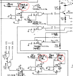
3. Add a couple spots for optional tantalum caps on the +5V rails in the video section which again is said to help with video jitters. I'm thinking between C11 and 12, by U38 and U51, and right below U60 which already has an open via on the ground bus.
4. And this one I'm really on the fence on, but since the 4MHz mod seemed pretty popular back in the day, and seems to work well on the original board I restored that had it, doing a few changes over in the Y2/U96 area of the board to allow for this mod without having to cut traces or bend chip legs out, and solder on additional wires. I think I can do it all via solder jumpers on the back side so it wouldn't change the appearance from above.
1. Fix all the v1.0 errata (missing traces), including the factory bodge needed on U73 (the video ROM).
2. I had a hard time getting a Goldstar branded 74LS123 working well in U38, until I cut the traces to ground on the Cext pins. This is mentioned in one of the Cornucopia articles and ground connections generally do NOT appear on the 74LS123 datasheets, with those pins already being internally grounded in the package. It's also hand annotated on one of the schematics for this board floating around on the net. Finally it would allow for easy use of 74LS221's in their place, which are fully temp and voltage compensated and said to help with video jitter in another Cornucopia article.

3. Add a couple spots for optional tantalum caps on the +5V rails in the video section which again is said to help with video jitters. I'm thinking between C11 and 12, by U38 and U51, and right below U60 which already has an open via on the ground bus.
4. And this one I'm really on the fence on, but since the 4MHz mod seemed pretty popular back in the day, and seems to work well on the original board I restored that had it, doing a few changes over in the Y2/U96 area of the board to allow for this mod without having to cut traces or bend chip legs out, and solder on additional wires. I think I can do it all via solder jumpers on the back side so it wouldn't change the appearance from above.
fdiskitup
Experienced Member
it was great to meet you at VCF, how many of these rev 1.0 boards are out in the wild now ?
have you tried swooping this out in the existing board ? - I'm at the shopping BOM stage - lots of 4116 ram chips on order from Aliexpress...Finally it would allow for easy use of 74LS221's in their place,
hideehoo
Experienced Member
it was great to meet you at VCF, how many of these rev 1.0 boards are out in the wild now ?
have you tried swooping this out in the existing board ? - I'm at the shopping BOM stage - lots of 4116 ram chips on order from Aliexpress...
All ten boards (including mine) are out in wild now, so far only @gekaufman and I have them built and working that I know of. Don't have any 72LS221's in stock, so no idea on how they work, on my next order from UTSource currently.
For 4116's, even UTSource is kinda spendy these days, so I rolled the dice on 70 of these, https://www.aliexpress.us/item/3256805415733599.html, figuring I could hopefully get 64 working chips. Got 71 chips is a loose bag, so lots of pin straightening, but only one tested bad so can't complain at $0.37/piece after shipping.
hideehoo
Experienced Member
Tonight's random KiCAD projects are a composite video board if you don't want to make your own cable
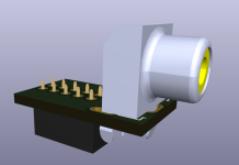
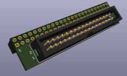
And a slimmed down version of the fd50to34 adapter that plugs directly into the 50 pin floppy header
Next up is a sixteen LED blinkem board for the J5 header to give the CTC and extra PIO something useful to do.

And a slimmed down version of the fd50to34 adapter that plugs directly into the 50 pin floppy header

Next up is a sixteen LED blinkem board for the J5 header to give the CTC and extra PIO something useful to do.
hideehoo
Experienced Member
Blinken Board
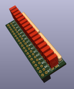
Yes, I'm driving the outputs high directly from the 74LS243's since there isn't a handy 5V source close by. With 470R resistors, each output is ~7mA for a total of 28mA per driver. Datasheet IL is -15mA at high (per output? total?) but I let one sit for an hour and nothing heated up so I'm going to say this will be fine. Hobby grade electrical engineering FTW.
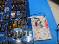

Yes, I'm driving the outputs high directly from the 74LS243's since there isn't a handy 5V source close by. With 470R resistors, each output is ~7mA for a total of 28mA per driver. Datasheet IL is -15mA at high (per output? total?) but I let one sit for an hour and nothing heated up so I'm going to say this will be fine. Hobby grade electrical engineering FTW.

Last edited:
Really fantastic work!
I really enjoyed seeing your work at VCFMW.
- Alex
I really enjoyed seeing your work at VCFMW.
- Alex
gekaufman
Experienced Member
Adapter boards look fantastic, nice touch! Your keyboard adapter is also great.
I recall always doing a 4mhz modification that just involved shifting two pins on the 74164. I'll have to look back as I don't recall the specifics. I always just built it up on a small header as I hated modifying the original pcb.
Did you try a 74F04 or 74S04 in the video oscillator circuit? Fixed the jitter on my board.
Interesting observation on the 74LS123's. I had some really nice looking 54123's that I tried to use and none worked in the BB1. Might be why.
hideehoo
Experienced Member
Adapter boards look fantastic, nice touch! Your keyboard adapter is also great.
I recall always doing a 4mhz modification that just involved shifting two pins on the 74164. I'll have to look back as I don't recall the specifics. I always just built it up on a small header as I hated modifying the original pcb.
Did you try a 74F04 or 74S04 in the video oscillator circuit? Fixed the jitter on my board.
Interesting observation on the 74LS123's. I had some really nice looking 54123's that I tried to use and none worked in the BB1. Might be why.
I've had a 74S04 in U11 on the new board and haven't really noticed a jitter issue on a CRT monitor. Original board had a plain 7404 for U11 and also seems fine (on a proper CRT). The extra caps are really just a belt and suspenders approach in case they are needed by someone.
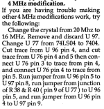
The 4 MHz mod on my original is this one from issue #3.
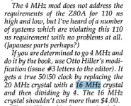
It requires changing the crystal, but seems to be the "proper" way to do it. Here's another blurb talking about this approach vs. some of the earlier approaches that still used the 20 MHz stock crystal. Kaypro did the same to get 4 MHz from the factory.
fdiskitup
Experienced Member
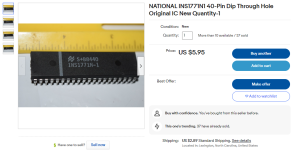
Next time you are over by this way check out "Chester Electronics in Kenosha, WI" - it's a real electronics shop with shelves and loads of LS logic, and real people who will go into the back storeroom and come back with hard to find components. However the one thing they did not have was the Floppy controller FD1771 : Fleabay currently has this NI alternate that should work. The DD mod starts to look more attractive ..even UTSource is kinda spendy these days,
hideehoo
Experienced Member
Next time you are over by this way check out "Chester Electronics in Kenosha, WI" - it's a real electronics shop with shelves and loads of LS logic, and real people who will go into the back storeroom and come back with hard to find components. However the one thing they did not have was the Floppy controller FD1771 : Fleabay currently has this NI alternate that should work. The DD mod starts to look more attractive ..
View attachment 1264273
Nice, and a great price, please let us know how it works out. I picked up this guy from eBay while I was waiting for my FD1771's from China, but unfortunately it didn't work.

National INS1771J-1 1771 Floppy Disk Formatter/Controller | eBay
Find many great new & used options and get the best deals for National INS1771J-1 1771 Floppy Disk Formatter/Controller at the best online prices at eBay! Free shipping for many products!
www.ebay.com
Not sure if the J and N variants are different (datasheets are a little thin on these), but could have just been a bad chip. Didn't take any time to scope or troubleshoot it since the FD1771's showed up a day later and are working great.
Still pondering breaking out the desoldering station and stripping down that SWP DD board. Or if anyone has schematics for one, should be pretty easy to replicate without a full teardown.
hideehoo
Experienced Member
Almost done with v1.1. Fixed all the errata, added some additional through hole pads between the various 5V and ground bars up in the video section to make it easy to add some additional caps (nothing is labeled, just there if you need them), and I did add the ability to easily do the 4Mhz mod referenced above with a series of solder jumpers on the back side of the board, so it doesn't change the look from the top side at all with the exception of some additional vias.


gekaufman
Experienced Member
Exciting news!
Did you also make the 74LS123 changes?
Looked thru Otto's 4mhz modification. One line is unclear - "run jumper from junction of R38 & R40 (pin 9 of U77) to U96 pin 5"
I assume it intended it to read the junction of R39 and R40, but even that isn't pin 9 of U77 (unless the schematic is again incorrect). Did you just jumper U77 pin 9 to U96 pin 5?
- Gary

