• Please review our updated Terms and Rules here

Recreating the Ferguson Big Board

Exciting news!

Did you also make the 74LS123 changes?

Looked thru Otto's 4mhz modification. One line is unclear - "run jumper from junction of R38 & R40 (pin 9 of U77) to U96 pin 5"
I assume it intended it to read the junction of R39 and R40, but even that isn't pin 9 of U77 (unless the schematic is again incorrect). Did you just jumper U77 pin 9 to U96 pin 5?

- Gary
Yep, the the Cext pins on the 74LS123's (and their associated caps) were isolated from ground in the video section. When I do a v1.1 validation build I'll try 74LS221's since it also requires a change in the capacitor and resistors values that make up the RC network there.

There is no electrical junction between R38 and R40 as you point out, figured that was more of a physical indicator of where you could solder a bodge wire on the board. Here's that mod in schematic form (confirmed with my original board) which is a little easier to follow. With 2Mhz and 4Mhz now coming from U96, you can remove U97 completely. The CAS and MUXC lines are shifted one bit "faster" on U76 due the slower 16Mhz crystal.

1695325602459.png

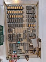
Here's what the U77 pin 9 / R40 "junction" change looks like. It's purpose is to move from U96 pin 4 to U96 pin 5 which is only a 4x divisor (vs 8x on pin 4) to get the 4Mhz main clock signal up to the CPU Then the additional traces/jumpers heading south route these 4Mhz and 2Mhz signals down to where U97 used to be to send them to the FD1771 floppy controller.

1695326018037.png
 
Next time you are over by this way check out "Chester Electronics in Kenosha, WI" - it's a real electronics shop with shelves and loads of LS logic, and real people who will go into the back storeroom and come back with hard to find components. However the one thing they did not have was the Floppy controller FD1771 : Fleabay currently has this NI alternate that should work. The DD mod starts to look more attractive ..
View attachment 1264273

Ordered a couple INS1771's from this eBay seller and they came in today. Seem to work fine.

I do have one weird issue unrelated to the disk control chip used where some Chinese sourced 74LS242's claiming to be TI chips from Portugal (and it's even molded on the back of the chip) refuse to work in the U100 spot on both my original and repro boards. Works fine in U99 right next door. But to get the disk working, I need to run one of the original Mitsubishi chips in U100. Scoped multiple copies with a 1Khz test signal, seem fine. Probably just sketchy examples with bad timing at higher frequencies, have some other brands/flavors in bound to do a little more mix and match testing.

Unfortunate the 74LS243 (non-inverting) versions still seem to be readily available, but the 74LS242 (inverting) are a bit more rare these days. I'm assuming 74LS640 octal inverting transceivers were also available in ~1980.

PXL_20230922_235009222.jpg

PXL_20230922_235032529.jpg

Also found another schematic error in this area, the inverter (U103) between U87 and the buffers is not actually connected (although the trace does run right by those pins on U103). Makes sense given U87 is a NOR and the 74LS242's do a read on active high to pins 1 and pins 13, but had to chuckle.

1695428516133.png
1695428999272.png
 
Last edited:
Last v1.1 change (I hope)...

I could never figure out why the low current/TG43 signal on the floppy interface was on pin 6 instead of pin 2. The SA800 didn't actually use it and, but the SA850 which was also available at that time had it on pin 2 and that seems to be the standard from what I can tell. Can't find an example of a drive that has it on pin 6. Micro Cornucopia calls this out in a letter on Qume DT-8 compatibility.

1695678957057.png

The reason I care is because I'm planning on (optionally, via solder jumper) bringing +5V out of pins 4 and 6 (generally unused on 8" drive interfaces) to power a custom Flash Floppy drive module (based on Open Flops) that plugs directly into the disk interface header. Could just stick with pin 4, but I always like the "more is better approach" with power.

1695679102339.png

Quick mock up for size. Hoping with some creative routing and different components I can get the height down a bit more still which sticking to 0805 and larger SMD components so this can stay a general hobbyist project.

1695679192214.png

Otherwise I may just do something like this, https://github.com/konkotgit/Mini-Floppy-Emulator, with a 50 pin interface that could hang off a short ribbon cable. The important part here is not have to deal with another power connector.
 
Accessory PCB's came in and all seem to work

Composite video adapter
composite-video-adapter.jpg

50 to 34 pin "mini" floppy adapter

50-to-34p-floppy-adapter.jpg

And the blinken board for the PIO port.

blinken-board.jpg

Video of it in action, did a little Turbo Pascal programming.


Github has been updated with files and build instructions. For anyone with a version 1.0 board, drop me a DM and I can send you the three PCB's if you want to accessorize your Big Board.
 
Custom FlashFloppy compatible PCB for the drive header is done. Will be shipping that and version 1.1 boards off the JLCPCB this weekend. Ended up going with a MicroSD card instead of USB to make it a bit more compact. FlashFloppy firmware supports both these days so hopefully that decision works out. Also ready to support dual drive emulation once that feature is baked into the firmware.

1697238467967.png

1697238509140.png
 
Board I bought at VCF Midwest has all the discrete components and sockets in place. Just gotta go through the errata then I can start placing ICs.

I kind of wanted to go all in on the 4116s for authenticity, but that's $60 from Unicorn and I have a spare generic PC multicard that's chock full of 2764 I could modify. Hmm.

I bought 70 of these, https://www.aliexpress.us/item/3256805415733599.html

Got 71, and only one tested bad. Just be prepared to straighten pins. Should be about $20 shipped for 40.

I also built one of these, https://github.com/zeus074/dramtester. So far everything that has passed on the tester has also passed the BB1 memory test. I have enough extra boards and parts to build a few more if anyone wants to build there own. DM me if interested, let's say $20 shipped in the US.
 
Great news on the V1.1 PCB!
Custom FlashFloppy also looks great.

You're very good at finding bargains on AliExpress. I also purchased 4116's from the same seller - Mine were desoldered and remarked - I tested them on a Neo-Loch tester and 15 were defective. Another 20 had rather short pins. That said, the seller quickly refunded 1/2 of my purchase price and I ended up with enough DRAM for a Big Board at a rather low cost. A very inexpensive option - just order some spares.
 
Anyone know what IC occupies u107? Maybe I'm missing something, but neither the google docs sheet nor the bitsavers scans of the original list it. From the photos I can find something is supposed to be there, but they're all too low resolution for me to tell what.

EDIT: I hit up the schematics. U107 is a 8116.
I'm a bit late to the thread here, and glad you were able to find it.
I looked at one of the photos I took for the Big Board I recently locally sold, posted in one of the FB groups. It is a 8116.
1700935789848.png
 
Hopefully this is not too off topic, but I am wondering if anyone has ever seen, copied, created, or shared 5.25" floppy images for the OG Bigboard, assuming one converted a 5.25" floppy driveto work like an 8" drive?

I have a Bigboard board that looks like an early board - the final outline was never trimmed on it. I also have (with no documentation) one of the Rivendell boards that was mounted to my BB1, giving me the impression that the entire setup actually functioned at one time.
 

Attachments

  • s-l1600 (1).jpg
    s-l1600 (1).jpg
    410 KB · Views: 18
  • Rivendell Audiocomp board.jpg
    Rivendell Audiocomp board.jpg
    86.5 KB · Views: 18
Last edited:
Back
Top