• Please review our updated Terms and Rules here

Removing C56 from IBM XT system board?

madmaxamdam

Member
Joined
Oct 25, 2012
Messages
24
Location
Italy
Well, after resurrecting an IBM PC, with the valuable help of many senior members of this forum, I'm now tweaking with this IBM XT 5160.

At minimum diagnostic configuration the power supply won't work, unless connector P8 is removed.

The readings on the board power connector are:
GND to +12V: 0.4 Ohm (steady value after a quick decrease)
GND to -12V: Infinite
GND to +5V: 198 Ohm (slowly increasing over time)
GND to -5V: Infinite

So it looks like the issue is on the +12V line.

I've read here that in this situation the C56 tantalum capacitor is very likely to be the faulty component. The suggestion is simply to remove it from the board.

A quick questions, before unsoldering:
Is that capacitor used for anything?
Can I safely give power to the board without that cap, or shall I replace it with another working cap?

Thanks in advance,
Max
 
You can remove the cap--it's used as a decoupling capacitor and there's very little (other than a few accessory cards and the async card that uses it). As the PSU also has filter caps on the line, you needn't worry about leaving the one on the planar out.
 
Thanks Chuck for your feedback!

So I just removed the C56, and the new measure GND to +12V on the board power conector reads Infinite.

Also, the resistance at the now removed C56 legs (center leg to lateral leg) reads some fraction of Ohms, so looked like the C56 was actually the culprit.

This all looked fine, so I tried again to power on with minimal diagnostic config. (i.e. both P8 and P9 inserted).
The power supply fan started to spin and then stopped again!

Something bad happened again.

Removing P8, the fan still turns, so there must be again something on the +/- 12V line...
 
Make sure that there's a load on the +12 from a hard or floppy drive. An XT PSU will shut down if too lightly loaded.

Just tried that, the results are the following:
1. P9 only = OK
2. P8 + P9 = KO
3. P9 + P10 = OK
4. P8 + P9 + P10 = KO

Legenda:
P8 = +12/-12V power supply to motherboard
P9 = +5/-5V power supply to motherboard
P10 = +5/+12 power supply to FDD

So it looks like the PSU refuses to work only when P8 is connected; this independent from other connections and from the total power load.

I'll have to take the motherboard out of the case again, and measure those resistance at power inputs, I'd not be surprise to find some other shorts happened at a previous power-on...
 
Well, now it's the GND to -12V resistance of the board is around 0.5 Ohm!
The same line read Infinite beforehand (look at Post#1 of this thread).

Please consider that after I removed C56 cap, at the first power-on with P8+P9 inserted the PSU fan started to spin, then after a while it stopped.
Now, when P8 is inserted, the PSU fan doesn't even start to move.

An easy solution would be to remove the -12V line cap too (i.e. the C59 cap), but its resistance (still connected to the board) is around 200 Ohm, so it doesn't look shorted actually...

What are the most likely components that could go wrong on -12V line?
 
None--there's nothing on the 5160 motherboard that takes -12. Any short is most likely a capacitor. Please be certain that when you measure resistance, you measure it twice--first one way, then with the probes reversed.
 
None--there's nothing on the 5160 motherboard that takes -12. Any short is most likely a capacitor.
I tend to see this as a good news, as it narrows the research...

Please be certain that when you measure resistance, you measure it twice--first one way, then with the probes reversed.
Ok, these are the readings:

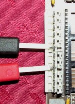
On board's power connector, when measuring GND to -12V (black probe on GND, red probe on -12V, see figure below) the multimeter reads 0.4 Ohm.
measure_minus_12.jpg
If I reverse the probes (black probe on -12V, red probe on GND) the multimeter reads 0.4 Ohm again.

On the C59 cap, when measuring with red probe on the center leg, the multimeter reads 199.6 Ohm (about 200, as I said earlier).
If I reverse the probes (red probe on lateral leg), the multimeter reads 114 Ohm - slightly less, but still not a short.

There's an identical tantalum cap nearby, which is the C58, that has a "suspicious" measure: it reads 0.5 Ohm with both probe settings. But I do not know if C58 has anything to do with -12V line. And an on-board measure is not always accurate in relation to the specific component under measurement.
Are there other candidates? Or are there any schematics for the power line connections on the board?
 
The problem with your measurements is that the -12 line just goes straight through the motherboard to the ISA edge connectors; there are no inductors or resistors to get in the way. In other words, all meausrements should be the same within a few tenths of an ohm.

Please double-check your measurements. If necessary, measure things at the ISA bus (http://pinouts.ru/Slots/ISA_pinout.shtml]Pinouts.ru has a nice diagram and description of the signals on the bus.
 
Measures at ISA bus (performed twice, by reversing the probes, and on the two outermost ISA connectors: J1 and J8, just to be sure):
B1(GND) - B3(+5V) = Infinite
B1(GND) - B5(-5V) = Infinite
B1(GND) - B9(+12V) = Infinite
B1(GND) - B7(-12V) = 0.7 Ohm

The last one is absolutely coherent to what I read at power connector (GND to -12V gives 0.5 Ohm there).

Therefore the "strange" measure (if I'm understanding what you say) is the one at C59 cap.
I did it again and the result is always the same: 199.6 Ohm (red on center) and 114 Ohm (red on lateral).

Now, I'm admittely a newbie, but please assume that I know how to measure a resistance, and that I can count pins (I may post a video just to show that :p).
Under such an assumption, what could be a possible reason for that?!?
 
Update: I've made further tests using continuity (multimeter beeper), and then measuring resistance, and it looks like C58 cap is absolutely involved.

All of the following points are connected (continuity beeps steadily) and give a resistance of about 0.5 Ohm in all possible combinations: C58 center leg, C58 lateral leg, power connector GND, power connector -12V, ISA bus B1, ISA bus B7.

In other words the C58 cap is shorted, and it is shorting GND and -12V.

Now is the C58 another "disposable" cap?...
 
As -12 is typically connected to nothing other than the Async card on later 5150s, the presence of C58 is irrelevant to the operation of the system.
 
I've got an Async card, that was plugged in this XT when I first opened it.
But I do not plan to use it: for the moment my goal is the awakening of the lady in her basic configuration: keyboard, CGA monitor, HDD and FDD.
Tomorrow I'll remove the C58 and let you know the results.
Thanks for your help so far!
 
I'd recently repaired two 5160 boards. If one cap is bad, there will be more bad.

I'd replace all tantal caps.
30 minutes of soldering and the board is as new. Only the three pin tantal
caps are bad. The small two pin caps (100n I think) never go bad... (these are not tantal)
See almost the last posting here:

http://www.vintage-computer.com/vcf...the-garbageman-(IBM-CGA)&highlight=garbageman

Regards, Roland
 
Last edited:
That's probably good advice, Roland.

Quality on capacitors in general seems vary by manufacturing run. So if you have a bad capacitor on a board, chances are that other similar capacitors on the same board are suspect.
 
If one cap is bad, there will be more bad. I'd replace all tantal caps.

Mmm...looks like this is what's happening with this XT board.
C56 shorted at first power on, then it was the turn of C58... I wonder who'll be the next. :)

Just for testing purpose, tonight I will try a further poweron with C58 removed. Since these caps go from powerline to GND my understanding is that they just provide voltage stabilization, preventing spikes coming from the PSU to reach the components on the option cards inserted onto the ISA bus.
As Chuck said, it should be safe to work without them until I'm just running the minimal diagnostic config.

Anyway, replacing all those caps will take more than 30 minutes to me: I am not THAT good at soldering... :p
Any suggestion on what kind of caps would work best in replacing those bulbish, three-legged, orange, tantalum caps (type, capacity, etc)?
 
Since these caps go from powerline to GND my understanding is that they just provide voltage stabilization, preventing spikes coming from the PSU to reach the components on the option cards inserted onto the ISA bus.
Pretty much.
Part of a distributed noise/riple filtering network.

Any suggestion on what kind of caps would work best in replacing those bulbish, three-legged, orange, tantalum caps (type, capacity, etc)?
1. Goto http://www.minuszerodegrees.net/failure.htm
2. In the 'Tantalum Capacitor' area, note the line, "Click here for information about the three-legged tantalums on the IBM 51xx motherboards/cards."
 
In the 'Tantalum Capacitor' area, note the line, "Click here for information about the three-legged tantalums on the IBM 51xx motherboards/cards."

My bad.
I'm spending some time on that very helpful site of yours ;) and still I didn't notice that reference.
Doing this stuff at night gets my eyes quite blurred... :)

I've just bought a handful of 2-legged tantalum caps 10uF-25V.
The storekeeper didn't even know that there is a 3-legged version (but using the 2-leg should not be an issue... as long as I mount them with the correct polarity).
Nor did they have 16V ones in stock. I've probably spent some cents more with the 25V, but this time they may last a bit longer.

Later today I will report whether removing the C58 brings the board back to life.

Then, if that's all ok, I'll brush on my soldering skills in order to replace the now missing C56+C58, and possibly "renew" the whole cap array as suggested by Roland.
 
Hooray! The old lady just let me hear her voice!
Tested twice, with C56 and C58 removed, and then after replacement by the brand new caps, and the Minimum Diagnostic Configuration always runs perfectly.
PSU fan is spinning like a charm and the beeps are beeping like a symphony.

@modem7: you may want to update the statistics page on your site with a new C56 + C58 case.
 
The problem with your measurements is that the -12 line just goes straight through the motherboard to the ISA edge connectors; there are no inductors or resistors to get in the way. In other words, all meausrements should be the same within a few tenths of an ohm.

Please double-check your measurements. If necessary, measure things at the ISA bus (http://pinouts.ru/Slots/ISA_pinout.shtml]Pinouts.ru has a nice diagram and description of the signals on the bus.

Whithout reading further, I'd like to say that it seems like a bad idea to just grab the ohmmeter and poke the leads onto the board. What if the ohmmeter puts out 6 volts and you test a five volt component? And yes, you always have to unsolder a lead to measure resistance of a component on a board. That's because the ohmmeter current can go through the circuit via other routes and give a correct reading for the series/parallel circuit that is formed when you attach the leads.

Another thing is that capacitors, when working correctly, show low resistance until and unless they are charged up by the meter current, whereupon they might go to near infinite resistance. They could also be charged up before the first measurement.

My 2 pence.

Sean
 
Back
Top