• Please review our updated Terms and Rules here

reproduction PDP 8e toggle switches?

I just received some custom made DEC white spray paint from MyPerfectColor.com to repaint PDP-8/e programmer's panels. $63 for three cans including shipping. I haven't tried it yet.

Hedrix Fast Dry Acrylic Enamel Spray Paint Match of Munsell N 9.5/ (Neutral Value Scale)

I took the paint code from Vince's documents.
 
Be aware that for a given set of RGB values, ...

There is a sense in which neither were/are the paint colors. Even a hue specification like "24.125" is only specifying the hue with an effective resolution of a couple hundred colors. (The space is carved into 24 slices, with a resolution of 1/8 in each one.) It was considered "good enough" at the time, and mostly gave a shared vocabulary for talking about color.

Unfortunately, the eye is scary good at telling close colors apart when they are held next to each other. (Fortunately, we are terrible at telling one shade of orange from another if we have to look at them one after the other.) So it's way easier to get acceptable "PDP-8/E colors" than to get something to match our existing machines.

Vince
 
I finished some major code cleanup today on these:
http://svn.so-much-stuff.com/svn/trunk/so-much-stuff.com/pdp8/repair/dec-std
http://svn.so-much-stuff.com/svn/trunk/so-much-stuff.com/pdp8/repair/dec-std.html

This replaces the Munsell color code that I had with table lookups. There's just not an easy algorithm that approximates the scheme well, as it's apparently all tweaked by artists to look right.

It also substantially cleans up the CHM code I had -- that scheme is fairly regular, but I rewrote the bits that compute the white and black content to perform correctly as I understand Ostwald's scheme.

I added some pretty tables at the front, which hopefully suggest that things are working.

Many of the colors in the DEC table look more like CHD's page now :).

Vince
 
Is the DEC spray paint from MyPerfectColor for the aluminium frame around the periphery of the 8/E programmer's panel?
 
Thanks for your hard work Vince.

A difficulty of colours!

I thought I would return to this subject and report what I have noted.

Here are two useful resources on the subject of how humans perceive colour… it is worth watching the YouTube video to understand what is going on.


These are some of the reasons why "on screen matching" against real-world objects tends to be hard and problematic, even if the screen and graphics card are properly "calibrated".

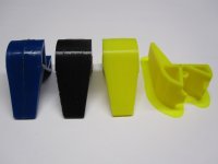
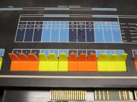
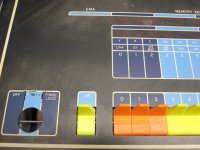
Another way to perform colour matching of real-world objects is to use "official" colour swatches (my work briefly intersected with this sort of activity many years ago). However, this is also subject to problems related to how the human eye-brain combo perceives colour. Below are two images of an "amber" handle against some "official" RAL colour swatches. The "daylight" image was taken outside in natural daylight, but on an overcast day (that’s what we have at here the moment). The other was taken inside under LED lighting. Spot the difference! It is even more obvious in person (probably because of the phone camera’s limited gamut and that it’s all RGB only).

00_daylight.jpg 02_LED_lighting.jpg

I believe the differences here are because of the variances in the wavelength coverage and intensity of light from the two sources and how much of these are reflected and absorbed by the different pigments in the two items (the swatches and the plastic of the handle)… Under florescent lighting it was different again; using the flash also makes it different again. In slightly brighter daylight the handle matched more closely with one of the other RAL swatches. I have been waiting for direct sunlight – but it is winter time here so that hasn't happened…!

The terra cotta handle in the images is a red herring as it does not appear to match well with any of the available swatches in the lighting conditions tested so far. Note that I also only have a small set of swatches.

I expect all this makes it hard to get a paint/paint-mix that can be used to paint a green/wrong colour switch so that it matches an original amber or terra cotta plastic handle under different lighting conditions. So it is probably a case of getting a "close" matching paint and then painting all the handles (for replacement purposes). Or, maybe, an "indistinguishable" amber/terra cotta paint for the wrong coloured switch under the lighting conditions the system will usually be seen under. One potential issue with painting the switches is choosing a paint that won't affect the plastic in a bad way, or chip/rub off too easily.

I will attempt a low-cost RAL paint mix at some point.

It is likely no easier to 3D print a handle using "colour mix-matched resin" (even if that is practical to do: WIP) that matches perfectly (so a complete set would have to be produced).

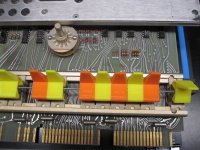
I have noticed in various photos that the colour of the handles is not an exact match for the legend colours on the panels… so, as long as all the handles are perceived as being the same colour as a set, a "satisfactory" colour choice is probably okay.

Note, also, that the current 3D model is not a precise match for the actual handles. I will look into trying to produce something with "OpenSCAD" at some point.
 
I finally started to feel like working on projects again. Spent the day doing a Fusion 360 parametric model of a paddle handle. See the attached jpg. The earlier one I did was in Sketchup which is a pretty terrible program for doing this kind of modeling. The model is as much like the real thing in its dimensions as I can make it but I have changed the wall thickness to make it a multiple of the nozzle diameter which will make it print faster. I've decided to print it on its side with some support. I am probably going to add a chamfer to the piece that flips the switch so it won't need any support material in that area. Unfortunately it will still need support on the side of the handle that faces the build plate. It will also need some support on the pivot area because that is recessed. That one doesn't matter cosmetically but it will need to be cleaned up to work smoothly. I was tempted to tighten up the tolerances because my original handles are a bit sloppy but DEC may have used different switches on the front panel over the years so if I want a part that should work on any panel I should just match the original dimensions.

Once I get a decent looking part I will post the .stl file to thingiverse so people can use it.

I still have to print some and make sure I have the angles correct. I don't have a good way to measure the angles so I just eyeballed them and punched the numbers into the table.
 

Attachments

  • paddle.jpg
    paddle.jpg
    86.9 KB · Views: 3
Thanks for your hard work Vince.

A difficulty of colours!
Thanks for your clear exposition of the difficulties. I was aware of this as an abstract problem, and have some indirect experience (color matches that "just aren't right"), but the swatches and a concrete example help.

Note, also, that the current 3D model is not a precise match for the actual handles. I will look into trying to produce something with "OpenSCAD" at some point.

Hmm. I spent a fair bit of time getting the model on my site to match the shape and angles and operating characteristics quite closely in side-by-side comparisons. Of course, that's with a commercial house printing them in sintered nylon, so I suppose results may vary with a different process.

Something similar happens with the PCB edge connector layouts for my board work, though. Even though I make them available, folks insist on re-drawing them for their own CAD libraries, and each individual gets to enjoy struggling with the fit issues all over again! (I'm aware of three such efforts.)

Vince
 
Thanks for your clear exposition of the difficulties. I was aware of this as an abstract problem, and have some indirect experience (color matches that "just aren't right"), but the swatches and a concrete example help.


Hmm. I spent a fair bit of time getting the model on my site to match the shape and angles and operating characteristics quite closely in side-by-side comparisons. Of course, that's with a commercial house printing them in sintered nylon, so I suppose results may vary with a different process.

Something similar happens with the PCB edge connector layouts for my board work, though. Even though I make them available, folks insist on re-drawing them for their own CAD libraries, and each individual gets to enjoy struggling with the fit issues all over again! (I'm aware of three such efforts.)
Apologies Vince; my note wasn't meant to come across as a criticism or complaint. It's the one found on Thingiverse when compared to an actual example that I was talking about. I wonder if different DEC "production runs" of them over the time might mean there actually were differences?

3D printing typically needs calibration for expansion/contraction of the resin/filament. I will go through that process and print yours off in resin.

A reason why I have modelling one in openSCAD on my mind is I am looking at them in terms of a (probably scaled) "look-a-like" version for an SBC6120 "front panel"; so the switch to which it mounts is likely to be different!
 
Something similar happens with the PCB edge connector layouts for my board work, though. Even though I make them available, folks insist on re-drawing them for their own CAD libraries, and each individual gets to enjoy struggling with the fit issues all over again! (I'm aware of three such efforts.)

I am guessing that I am one of those three at least for the handles. And I have now done it twice! I am going to claim that my reasoning is that the originals were designed to be injection molded, not 3D printed and I am trying to figure out how to make them more easily printable. You get solid parts when you injection mold and this is hardly necessary for what we are talking about here.

And I just spent another hour pondering how to make it better than the originals. The fit of the originals is actually quite poor when you look at it with some OCD getting in the way.

One thing I noticed this morning is that two of the switches on my front panel have detents while the rest do not. The ones with detents are the one labeled SW at the far left which I think of as the boot switch and the SING STEP switch second from the right. I assume this is because those were not spring loaded and matter quite a lot when the machine is running. I would have placed the HALT switch in this category as well but it does not have the detents.

On the issue of color. colorFabb https://colorfabb.com/custom-colored-pla-filament has a selection of RAL colors available and will make any color you specify. For a 750 gram spool it is about 50 euros which is about 3 times as expensive as off the shelf from Amazon sellers if it is a color they already have. This would be enough plastic to make about 187 handles. It looks like the minimum for a custom order is a 2 kg spool at 90 euros which is about twice the typical price. That is enough to make over 500 handles. A few years ago the minimum order was for 10 kg so this seems like a lot better deal. On a per piece basis this is around 30 cents per handle for the plastic including shipping. I have not talked to colorFabb about custom stuff and the website is a bit vague about these details so it could end up being more. Filabot https://www.filabot.com/pages/custom-color-matching-service?gclid=CjwKCAiAt9z-BRBCEiwA_bWv-J88J-QHidCnsyNcSJzClMuBlpPPFY630BGW_pHHv8Fw_wP7FELk1hoCsjYQAvD_BwE also has this as a future product on their website.

I was able to find close enough matches for me for the dark blue and light blue colors on the DECset 8k version of the 8/e. I am pretty sure most people would be happy replacing all their switches with a good enough color match. We just have to find something close enough. I am almost certain that the colors on the front panel do not match the handle colors under different lighting conditions.
 
I am guessing that I am one of those three at least for the handles. And I have now done it twice! I am going to claim that my reasoning is that the originals were designed to be injection molded, not 3D printed and I am trying to figure out how to make them more easily printable. You get solid parts when you injection mold and this is hardly necessary for what we are talking about here.

Don't mind me -- I was just being grumpy in the middle of the night :).

I do understand that (unlike the PCB scenario I mentioned) different processes yield different results. And after all, it was my own dissatisfaction with Shapeway's prints of phooky's design files that spurred my own round of tweaking.

The handles on my web site are adequate, but the fit isn't that good -- the holes are off a tad. As you point out, they don't print super well on inexpensive printers, etc. I didn't spend nearly the effort to get them "right", as they are a hidden thing you only deal with once, whereas the switch handles are front and center when it comes to attention.

One thing I noticed this morning is that two of the switches on my front panel have detents while the rest do not. The ones with detents are the one labeled SW at the far left which I think of as the boot switch and the SING STEP switch second from the right. I assume this is because those were not spring loaded and matter quite a lot when the machine is running. I would have placed the HALT switch in this category as well but it does not have the detents.

Interesting. I hadn't caught that detail.

Vince
 
I don't have a complete set; but now that you have mentioned it one probably does have detents - it locks up/down in a positive manner and clicks slightly when toggled. Whilst the rest of the unsprung ones are not sloppy in operation they don't "engage" like that one, I had assumed the others were "worn". If that's the case, I think this feature might be part of the switch's mechanism because, as far as I can tell, the handle is the same on all of them?

The resin printed "replacements" look superior to the filament type prints and also require less after-print fuss (already smooth and no layer lines). I posted about this somewhere above (complete with some pictures).
 
I printed a handle in black using draft settings. These are a 0.2 mm layer height with a 50mm/sec print speed. Took about 14 minutes and weighs a little over 2 grams. It looked ok but I decided that if you are going to do these you might as well try to make it look good. I printed a second one in black using a slower speed of 25mm/sec and a 0.12 mm layer height. This took 32 minutes to print. I had a pretty bright yellow so I printed two in that color. I was about to print a dozen in the orange color I happen to have laying around and realized I didn't even know if they would fit. I took my front panel apart so I could check fitment. Good thing I checked because the clearance on the pivot pin is non existent. I need to loosen up the tolerances just a little. Find attached photos of an original and the three I just printed.

Fixing it should be as simple as changing one or two numbers in the parametric table and generating a new .STL file.

Leftmost paddle is the original dark blue paddle from my DECset 8000. The black one is the first higher quality print. I changed the printing order so the outer surface is not printed first on the yellow ones. The rightmost one still has the brim and supports attached. This is what they look like coming off the printer. It takes less than a minute to clean these up. The most I would do beyond this is to sand the sides of the handle as they are rough on the right side from the support material and the left side has small stairsteps from the layers. To do much better would require going to a smaller diameter nozzle and an even finer layer height. At that point you would be looking at an hour per piece print time.
 

Attachments

  • paddle1.JPG
    paddle1.JPG
    90 KB · Views: 5
The first attachment is the side sketch from Fusion 360. If I did it again I could probably make it a little less cluttered with dimensions. The dimensions were entered into the table in inches but I prefer to use metric because the 3D printer uses metric for its native units. The next two attachments are the photos of the printing of 10 pieces of yellow and 10 pieces of orange. I placed a couple of the yellow paddles with the orange ones on the print bed for the photo. The yellow one in the front has not been cleaned up and you can see the support material on the right face of the handle facing up. The colors were not chosen to try to match the 8/e paddle colors. They are just what I happened to have. The brand is MagicSpace but that won't do you any good since that brand doesn't appear to be available anymore. I got a rainbow of colors in that brand when they were $15 for a kilo of each color. And even if it was an exact match for the paddles the next spool would be slightly different in color.

It took longer than I expected to fix the problems I found when I actually tried to mount the test print pieces on the front panel. It is somewhat tricky to measure the angles on the original parts so I ended up printing several test pieces until I got one where the handle in the raised position aligns with the original handles. It did end up being a change to just two numbers in the parametric table. I did have to change how I had one external face attached because it moved when I made a change to one parameter.

It takes more than a minute to clean up each part. More like between 3 and 5 minutes. All the time is spend removing the support material along the right side of the paddle. I am going to see if I can change how this support is printed to make it easier to remove. The support material under the pivot pin area just pops right off.

Next up is final assembly to verify that the replicas work as a whole. I found some 1/16" (1.59 mm) OD copper tubing which is what I plan to use as the replacement pivot pin. I looked for an aluminum tube or even aluminum rod but have not found anything off the shelf. The tubing came from my local ACE hardware. I found brass at the local hobby shop. I am going to check craft stores to see if I can find plastic rod in the correct diameter. I also have brass and steel rod material in the correct diameter as a fallback. Those are easy to find, at least in the USA.
 

Attachments

  • paddle 1 v5.jpg
    paddle 1 v5.jpg
    90.1 KB · Views: 7
  • IMG_2190.JPG
    IMG_2190.JPG
    246.2 KB · Views: 6
  • IMG_2191.JPG
    IMG_2191.JPG
    211.2 KB · Views: 6
The 3D model is based on measurements taken from original paddles. But when I was having problems with the fit I decided to try to find the drawings of the switches. The first photo is of the rightmost switch which is the deposit switch. The spring loaded switch part number is clearly 028-420-0002. Unfortunately, I was not able to get any search hits that were not from vendors claiming to have this part in stock but no information about the part. There were at least 5 different companies whose web pages were suspiciously similar. Airpax appears to still exist as a company but no longer manufactures switches. I have not tried to contact them to see if any old documentation is still available. Note that there is some corrosion on the side of the switch. This machine does not generally show much of its age as you will see from some of the other photos of the front panel assembly.

The second photo is of the right side of my 8/e front panel board with the yellow and orange switches fitted. I ran a piece of 1/16th inch piano wire through the length of the switches to hold them in place for this test. If this works when assembling the machine it is what I will use as it is a LOT easier and less stressful on the switches than bending the arms open to allow the original handles to be put back. There was probably a special tool. The problem is that the wire might have an interference with the back side of the front panel. I won't know for certain until I try to put the front panel back into the machine.

The third photo shows the switches peeking out through the front panel of the machine. This is the front panel from the decset8000 variant of the PDP-8/e which I think is the rarest of them. The only difference I can see is the front panel faceplate, switch paddle colors and a couple of custom boards that allowed the machine to interface with the digital typesetter. This 8/e variant appears to have been marketed to small newspapers to manage their classified ads.

The fourth photo was included to show that the spacing left to right is not even. This is entirely due to the arms of the switches being bent slightly. In the case of this front panel assembly they are all bent to the right when they are bent. I didn't do this so it must have been done either during assembly or at some previous time when paddles were replaced. At arms length you don't notice it. Someone used a pencil to make an up arrow on the 7 and 11 bits. I have tried to remove this with an eraser and most of it came off. What is left is mostly a smoothing of the surface finish which can't be easily fixed.

The fifth and last photo was included to show a couple of things. First, the wear and tear on the front panel. I did wash it using Dawn detergent and warm water but this didn't actually seem to make any difference. The area around the power switch is the worst. Probably a combination of skin oil and mechanical abrasion. The second thing is the ripple on the vertical face of the paddle under the handle. On poorly tuned printers you never see this. It is caused by the non linearity in the micro steps used to make the fine moves in stepper motors. You can get rid of most of it by changing from 1.8 degree stepper motors to 0.9 degree motors. I have done this on my scratch built core XY 3D printer which is probably where I will end up printing these if people want to buy some. The machine I used to print these handles is a Creality CR-10 with about $400 of upgrades. I should probably throw another $80 at it and fix this issue as well.

The operational feel is better than the original as there is less slop when using the piano wire as the pivot than the original pivot pins. I am quite happy with the way it has turned out.

I have a piece of 1/16th inch brass rod and 1/16th inch OD copper tubing. My plan is to use the copper tubing as it is soft enough that it will deform on an impact rather than break stuff. If the copper tubing is too fragile I will use the brass rod. The steel piano wire is the least expensive solution.

More news later!
 

Attachments

  • AIRPAX.JPG
    AIRPAX.JPG
    165.7 KB · Views: 12
  • IMG_2194.JPG
    IMG_2194.JPG
    184.9 KB · Views: 10
  • IMG_2196.JPG
    IMG_2196.JPG
    204.1 KB · Views: 9
  • IMG_2197.JPG
    IMG_2197.JPG
    231.8 KB · Views: 8
  • IMG_2198.JPG
    IMG_2198.JPG
    217.5 KB · Views: 9
Looks good. Have you considered eventually having some printed up in resin?

The ones that are not spring loaded have part number 028-420-0001. The ones with "detents" are also 028-420-0001 and look the same as the other 028-420-0001 parts.
 
Back
Top