• Please review our updated Terms and Rules here

Restoring a PDP-8/L

What you are seeing is pretty normal for a restoration. Replace a bunch of ICs, get everything working. A week later it doesn't work. Rinse and repeat. After a while you will find all of the failing ICs and it will run for years without a failure.
 
What you are seeing is pretty normal for a restoration. Replace a bunch of ICs, get everything working. A week later it doesn't work. Rinse and repeat. After a while you will find all of the failing ICs and it will run for years without a failure.
The 8/L restoration experience is completely different than the Omnibus hardware, which has been incredibly reliable. I'm wondering if it would be a good strategy to leave the CPU powered for days to shake out the remaining weak parts. I should research this.

Mostly there have been a bunch of bad ICs. One problem that worries me though, is the rusting transistor leads problem reported by @anders_bzn in his 8/L restoration log, on what looks to be a G221 Memory Selector. I also found one transistor with this issue but there might be more just about to fail.

Fortunately I have a good-sized spares kit. Haven't yet found a bad board in the spares kit.
 
I restored a pair of pdp8/L's last year, I should fire them up and see how they are doing. Didn't have a super board tester but did have a TTL chip tester which sped up finding problems a *LOT*.
Yes, a chip tester is also quite handy. I've seen a couple of these that look interesting. One is a small hand-held unit that will even identify the type of IC that's plugged in. The other is called the Retro Chip Tester.

I ended up building a small IC Test Jig with a 28-pin ZIF socket that plugs into the Flip Chip tester. The socket accepts parts from 0.3" to 0.6" wide. It's a variant of a board that Vince has on his site. Vince also has some test files that I adapted for the pinout of the IC Test Jig board, and added a few more test files for ICs in the 8/L and some in the 8/E. The Gerber and test files are on github.
 
A number of PROM programmers also have chip test capability. I have an EEtools Topmax II with a DIP 48 socket, and it has test capability for a wide range of TTL devices (DRAM, SRAM, 74 series logic). The test vector development language is quite simple, and I have written custom tests for DEC 8641, 8640, etc devices. Example:

Code:
.DEC8641 16
L1HL1H0G0H1LH1LV
Z0XL1H0G0H1LH1LV
00HL1H0G0H1LH1LV
10LL1H0G0H1LH1LV
L1HL1H0G0H1LH1LV
L1HZ0X0G0H1LH1LV
L1H00H0G0H1LH1LV
L1H10L0G0H1LH1LV
L1HL1H0G0H1LH1LV
L1HL1H0G0X0ZH1LV
L1HL1H0G0H00H1LV
L1HL1H0G0L01H1LV
L1HL1H0G0H1LH1LV
L1HL1H0G0H1LX0ZV
L1HL1H0G0H1LH00V
L1HL1H0G0H1LL01V
Z1XZ1X1G0X1ZX1ZV
Z1XZ1X1G1X1ZX1ZV
00HZ1X1G1X1ZX1ZV
11LZ1X1G1X1ZX1ZV
Z1X00H1G1X1ZX1ZV
Z1X11L1G1X1ZX1ZV
Z1XZ1X1G1H00X1ZV
Z1XZ1X1G1L11X1ZV
Z1XZ1X1G1X1ZH00V
Z1XZ1X1G1X1ZL11V
Z1XZ1X1G1X1ZX1ZV
Z1XZ1X0G1X1ZX1ZV
L1HL1H0G0H1LH1LV
 
A number of PROM programmers also have chip test capability. I have an EEtools Topmax II with a DIP 48 socket, and it has test capability for a wide range of TTL devices (DRAM, SRAM, 74 series logic). The test vector development language is quite simple, and I have written custom tests for DEC 8641, 8640, etc devices. Example:
Interesting. I didn't know that PROM programmers had this capability. My company always had DATAIO programmers and I only programmed PROMs, EPROMS, PALs and GALs. It's been a "few" years since I've used one.
 
More stuff is running now. Adjusted the timing of STROBE FIELD 0 (by adjusting the screw on the M360 delay in slot C17) so the pulse ends at about the peak of the data pulse out of the sense amplifiers. Now the data read from core memory is sampled at the point where the signal is strongest. BTW, memory cycles are being initiated by flipping switches on the front panel because I can't reliably run programs yet.

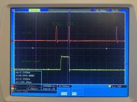
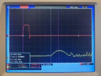
Next problem: MB09 was always zero after the first read. After writing a one to bit 09, the data pulse was visible at the output of the sense amplifier. The top trace is I think MEM START and bottom is pin 10 of the sense amplifier corresponding to bit 09.
IMG_8243.jpg
However, on the second read there was no data pulse! Problem was the sense amp strobe enable wasn't working and data wasn't being latched on the G020 card. But the G020 card had a yellow sticky dot so it was tested in the FlipChip tester. Turns out I apparently forgot to copy the updated G020v2.TST to the SD card in the tester and didn't fully test the board. Swapped in a good one from the spares kit since I don't have a spare MC1540 amplifier chip. Confirmed that G020v2.TST does fail the bad G020 that was removed.

Tried to run a "Hello World" program but discovered memory was not reliable around location 200. Put that on the to-do list. Higher pages seem reliable, so put Hello World at 7200. Now, something is crazy: monitoring the serial output on the scope, the string pointer starts at the second character and each character value is one more than the value it should be (so: instead of "Hello..." it was "Ifmmp..."). Happy I can see some characters coming out of the M707 Teletype Transmitter. Even though it's not quite correct, at least a lot is working for this to happen! By single stepping it's obvious that the TAD instruction is computing the proper value plus 1. In high memory the following program was used for debugging:
7400 1202 TAD 7402 7401 5200 JMP 7400 7402 0000
Started by tracing data through the paths on the M220, looking first at the LSB. It was properly selecting MEM11 and AC11 for the adder inputs. The AOI gates send one's compliment of data to the SN7482 2-bit adder chip. The adder output and AC11 are of course toggling like crazy. After a few minutes of drawing logic diagrams and following examples with pen and paper it's apparent that taking one's compliment of adder data inputs and inverting the carry input produces the one's complement of the sum. (This one's compliment of the sum is inverted again by another AOI gate to become the REG BUS value which is saved in the AC. The bit 11 adder carry input, "CARRY INSERT" was low at the rising edge of the AC LOAD pulse. This isn't right, because all inputs to the adder should be inverted data. Traced that back to the M160 AOI gates in slot A12. Checked all inputs and confirmed the AOI output should be "1", but the output is "0", which injects a carry into the adder which adds one when it shouldn't. This M160 has a yellow sticky dot so it was tested in the tester! Put the M160 back in the tester and it passes! Can't be! It fails in the machine but passes in the tester. Carefully studied the test program steps that test pins M1 N1 P1 and realized there's a bug. The test vectors skipped over the case of the bad input that exists on this board. Modified M160.TST with a simple fix and now the bad M160 fails in the tester, and a good M160 from the spares kit passes in the tester. Swapped in the good M160 into slot A12, and now the TAD instruction works properly. It appears to have been a bad SN7460 AOI expander gate on the M160.

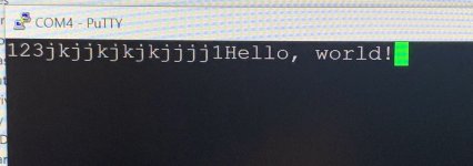
Connected a USB to CMOS serial cable to the M707 TTY Transmitter output, fired up Putty and set baud rate to 110 bps. Ran the Hello World program and...
IMG_8279.jpg
(The 123jkjj... are from me testing the serial cable with a wired loopback.)

Next step, test the serial receiver using a serial echo program.
Also, there's still the issue with slightly forgetful low memory pages. And there was an older issue with memory bit 04 that would occasionally be one when it shouldn't. maybe that's related to the low memory page flakeyness... need to investigate.
 
Interesting. I didn't know that PROM programmers had this capability. My company always had DATAIO programmers and I only programmed PROMs, EPROMS, PALs and GALs. It's been a "few" years since I've used one.
I use a cheap MiniPro TL866II Plus which has a "Logic IC Test" feature.
It supports most 7400 series TTL ICs but you can also add user defined ICs.
I use it much more for testing than for programming. :)
 
Testing the TTY receiver using a simple echo program. Characters typed on the keyboard are echoed to the terminal and also displayed in the AC register lights.
Code:
Terminal Echo Program
7640    6030        KCF        /Clear the ready flag
7641    6031        KSF        /check and skip on ready
7642    5241        JMP 41    /loop if not ready
7643    6036        KRB        /read the character from the TTY
7644    6046        TLS        /output the character to the TTY
7645    5241        JMP 41    /loop to get the next character

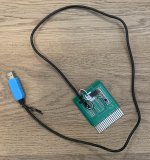
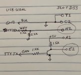
Realized that the M706 TTY Receiver needs data inverted from the standard present-day USB to CMOS serial cables, so I built this little device as a temporary test tool to plug into slot D33 in place of the W076 TTY-cable. There's a CP210x USB to UART bridge chip inside the blue connector shell. The PCB is from another project (an IC test jig for the Stearns Flip Chip tester). I just needed a board with a Flip Chip connector to build this simple circuit.
IMG_8288.jpg IMG_8289.jpg

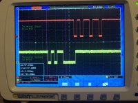
Characters were being looped back but bit 05 is stuck at “1”. In the image below a “return” is typed, 00001101. In this example, the 5th and 6th bits of the echoed character were changed to “1”. The 5th character bit also happens to be PDP-8 bit 05.
IMG_8280 with signal text.jpg

Followed bit 05 from the M706 TTY receiver, through the M220 Major Registers for bits 4 and 5 to the AC05 bit. There are two AC LOAD pulses around the time of the M706 KEYBOARD SELECT pulse. The first AC load is at the end of IOP B and the second is at the end of IOP C.
IMG_8287_with_text.jpg
It appears that bits in the AC should be cleared at the first AC LOAD. Confirmed this by typing a “1” and a “2” to see bits AC10 and AC11 set and clear. At the second AC LOAD pulse, the INT I/O BUS is added to AC. Bits 10 and 11 of AC are cleared at the first AC LOAD pulse because it’s before KEYBOARD SELECT so no data is being routed by the AOI gates on the M220 board during the first AC LOAD pulse at time IOP B. However, there was a “1” on INPUT BUS 05 during the first AC LOAD pulse (at the end of IOP B) that was causing AC 05 to be set to "1". Discovered this was due to INT I/O BUS 5/ being driven low at that time. Realized that there’s an M7050 Reader Control board in slot AB30 that has not been tested in the Flip Chip tester. Removed all of the reader and punch boards (M715 in AB29, M7050 in AB30, and M710 in AB31). I don’t have a paper tape reader/punch anyway. There are also two additional logic gate boards that don’t appear to be part of the standard PDP-8/L, which are an M111 in slot A34 and an M906 in slot B33. I suspect they are part of the reader/punch interface but I didn't remove them.

Now, without the reader/punch interface installed, bit 5 is not stuck at one and the TTY echo program properly echoes characters.
Next thing... investigate flakey low memory pages.
 
Back
Top