Quick summary up to this point:
- Large electrolytics have been reformed.
- +5V logic supply has been thoroughly tested with up to 8.7 A load with input voltage from an adjustable lab supply. Verified the Vout vs Vin characteristic and confirmed the spike exists as others have documented. Verified the OVP crowbar trip voltage = 6.59V. Built and tested Rolands 8/L crowbar but haven’t yet installed it in the machine.
- All of the Flip Chip modules have been cleaned and tested using the Stearns tester (ESP32 version). Made some updates to scope loop test vectors for some M-series modules with delay and pulse circuits and updated tests for some G-series modules. The updated TST files and documentation are in github.
Final power supply testing:
With the power supply removed from the chassis, finally plugged it in to AC power, actually into a KILL A WATT meter, so I know how much current this draws from the AC line.
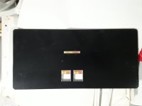
Built the following simple test jig to connect loads to the supply outputs at the G785 edge connector.

The 8/L power supply harness connects all of the output voltages to the backplane through the double-size G785. To test the power supply, the G785 was disconnected from the backplane and plugged into the test jig.
Connected two Kunkin electronic loads and various combinations of 8 ohm 50 W resistors to the supply outputs through the jig:
- 8 ohms 50 W to +7V (Panel Lights)
- 8 ohms 50 W to +5V (Logic) already tested with a lab supply and electronic load up to 8.7 A
- Kunkin Load #1 to -15V (keys & switches, sense amplifier)
- Kunkin Load #2 to -30V (memory negative supply)
- 8 ohms 50 W to -6V (memory positive supply) later learned this needs to sink to mem neg suppy)
They all tested okay except I wasn’t able to verify the -6V memory positive supply because it needs a load between -6V and -30V, and the memory positive (-6V) needs circuitry on the G826 Regulator Control board.
Front panel board bench testing:
Lots of cleaning first. Then…
Connected a +5V supply and +9V supply to the front panel board and verified every lamp driver input from the edge connector to verify the corresponding lamp would go on and off. Found 5 bad lamps, 3 bad driver transistors and I broke a 1K resistor during the repair process.
Connected a +5V supply and -15V supply to the front panel board and verified every switch could control its corresponding output on the edge connector.
Core quick test:
Verified about 25% of the diodes using the TC1 Multi-function Tester.
Put everything back into the chassis: power supply and needed to remove the A-row of Flip Chips to fit the supply back in the chassis. Front panel board and core memory modules and A-row Flip Chips installed.
Powered up the system. The noise of 3 fans is loud. System draws 1.59 A from the AC line.
All 12 address bits seem to work; loaded 0001, 0002, 0004, 0010, etc. up to 4000. Incremented through every carry to the next higher bit: 0001 to 0002, 0003 to 0004, 0007 to 0010, 0017 to 0020, etc. up to 7777 to 0000.
Could kind of store some data to memory, but bit 4 was stuck at one and I think the MSB or next MSB might have been always zero. Not sure if this was a core problem or data path issue. Should have taken a methodical approach to work through this. Instead, thought I’d try my spare core stack because it looks much newer and cleaner. Didn’t work though. Memory data always reads 0220, so bits 4 and 7 are stuck at one. Put the original core stack back in and now it does the same thing… always reads 0220.
Time to dive in and track down what’s happening, or what’s not happening.


")
