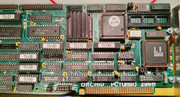
I have two non-working PCturbo accelerator boards that I’ve been trying to revive. These boards are particularly interesting as they do not use a cable to connect to the CPU socket but are instead able to control the 8088 and use it for I/O. On startup the PCturbo board holds the 286 in reset. You then need to run a driver program called “turbo.com” that sets up a shared memory location (default E000h) and copies across to the board an 8K bios image embedded in its .com file. It then takes the 286 out of reset and at this point execution switches to the board and you now running on the 286.
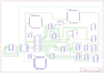
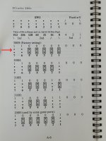
I’ve been building on this initial work of @per and have setup a Github repository (https://github.com/retrobyte83/pcturbo) where I now have a reasonably complete disassembly of turbo.com and a partial disassembly of the bios code, made using IDA. I also have a partial schematic from buzzing out most of the key traces, including everything that goes to the two 40-pin extension headers (address lines, data lines etc).
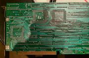
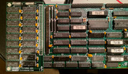
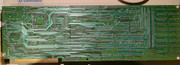
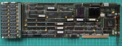
Board 1
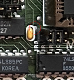
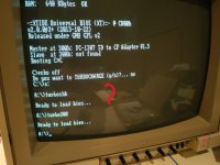
This is the board I first talked about here. When I got it, I found that the 286 had been installed in the wrong orientation. I’ve subsequently tested the CPU in another machine and it is fine. I’ve also debugged the startup to the point where the bios has been copied across to the PCturbo and the CPU starts running on the board, but after a bit it halts and the turbo.com driver errors out with “PCturbo not responding”.
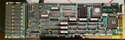
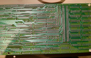
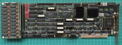
Board 2
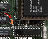
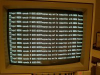
This board I got recently from @Mike1978 . It was DOA when he first got it, and having done some testing myself I can confirm there are no signs of life. The turbo.com driver errors out with “Cannot access the PCturbo”, which is what it would do if no board was installed.
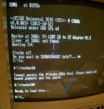
My hope (with some help!) is to try and use the different behaviour of both boards to progress the troubleshooting. My focus is currently on board 2, since it doesn’t seem to even get anywhere. I’m hoping if I can fix this initial issue, maybe it will spring into life or at least it might give me some direction on board 1. Given they behave differently, I’ve extracted a minimal code path from turbo.com into a small test executable “turbochk.com” which runs to the point where the behaviour diverges. It does some initialisation and then tests writing and reading back some bytes at the start of E000h. On Board 2 this check fails, but on board 1 it succeeds (and would start to copy across the bios beyond this point).
Unfortunately, I’m still a relative novice when it comes to x86 assembly, and it’s not clear to me exactly what is happening in the code to ensure the board maps memory to E000h, so that the read/write check passes. I’ve attached the code (turbochk.asm) and would welcome any thoughts. My next step in the meantime, is to swap the memory extension between the boards but I’m loathed to do too much further swapping around of parts until I better understand exactly what is going on.
I’ve been building on this initial work of @per and have setup a Github repository (https://github.com/retrobyte83/pcturbo) where I now have a reasonably complete disassembly of turbo.com and a partial disassembly of the bios code, made using IDA. I also have a partial schematic from buzzing out most of the key traces, including everything that goes to the two 40-pin extension headers (address lines, data lines etc).
Board 1
This is the board I first talked about here. When I got it, I found that the 286 had been installed in the wrong orientation. I’ve subsequently tested the CPU in another machine and it is fine. I’ve also debugged the startup to the point where the bios has been copied across to the PCturbo and the CPU starts running on the board, but after a bit it halts and the turbo.com driver errors out with “PCturbo not responding”.
Board 2
This board I got recently from @Mike1978 . It was DOA when he first got it, and having done some testing myself I can confirm there are no signs of life. The turbo.com driver errors out with “Cannot access the PCturbo”, which is what it would do if no board was installed.
My hope (with some help!) is to try and use the different behaviour of both boards to progress the troubleshooting. My focus is currently on board 2, since it doesn’t seem to even get anywhere. I’m hoping if I can fix this initial issue, maybe it will spring into life or at least it might give me some direction on board 1. Given they behave differently, I’ve extracted a minimal code path from turbo.com into a small test executable “turbochk.com” which runs to the point where the behaviour diverges. It does some initialisation and then tests writing and reading back some bytes at the start of E000h. On Board 2 this check fails, but on board 1 it succeeds (and would start to copy across the bios beyond this point).
Unfortunately, I’m still a relative novice when it comes to x86 assembly, and it’s not clear to me exactly what is happening in the code to ensure the board maps memory to E000h, so that the read/write check passes. I’ve attached the code (turbochk.asm) and would welcome any thoughts. My next step in the meantime, is to swap the memory extension between the boards but I’m loathed to do too much further swapping around of parts until I better understand exactly what is going on.
")