• Please review our updated Terms and Rules here

Reviving the PDP-12 at the RICM

We are back to working on the LINCtapes in the PDP-12. They sometimes work OK, but most often don't. Sometimes we can mark a tape, but usually can't. One issue is glitches on a data track that we have not been able to trace or fix. We have swapped the TU56 for a TU55, including the data cable, but there was no change. We swapped all of the boards in the read section of the TC12 tape controller and saw no improvement.

Another issue is skew on the tape head that we replaced. On Saturday we measured about 5uS of skew using quite a few tapes that were were written by DEC. The head signal is about 5mV, so it is at the limits of my 'scope. There is also a large amount of 25mV RF noise mixed with the head signal that makes it difficult for the 'scope to sync on the head signal. We haven't been able to reduce or find the source of the RF noise.

The DEC head skew correction procedure calls for turning the tape over so it is oxide side up. This will reduce the head signal to about 1mV, so I don't think that my 'scope will be able to see it. The DEC skew procedure describes an amplifier for the head signals. I think that we will need to make one so my 'scope can see the 1mV signal. We will probably add a low-pass filter to the amplifier to eliminate the RF noise that we see.

We will use the old TU56 head with the open MARK coils to hunt for the RF noise today. That may be an impossible task, but it is worth a try.
 
Naturally there'll be a fair amount of mush floating around a running pdp-12 (a bit less stringency in the way of FCC rules in the '60s ;) ) so it's hardly surprising that you're seeing a bit of high-frequency noise. I'd expect the read circuitry to reject it of course and the tape signals are pretty low frequency so easy to filter. I don't think it'll be much trouble to put together a low(ish) noise amplifier with a gain in the 10-100 range for the frequencies you're interested in using an op-amp. I think I might aim for low current consumption and run it from a battery to keep ground loops down.
 
We tried running my 'scope from the internal battery to make sure that the power supply was't part of the problem. It was not any quieter.

We tried my TU56 at home, and it is a lot quieter, but still noisy.

I pulled some G888 modules from a TC08 that I have. We will use the first stage Op-Amp to amplify the head signals and give it another try. If this doesn't filter the high frequency noise we will make a new amplifier using a modern Op-Amp and add a low pass filter.
 
If this doesn't filter the high frequency noise we will make a new amplifier using a modern Op-Amp and add a low pass filter.

You can't do that on all the channels, though, since up to speed depends on the G888 self-oscillating. One of those things I've wanted to fix.
I've never liked the positive feedback on G888s second gain stage.
 
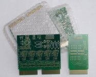
Last year me and Mattis tried to build a USB-TU55 interface. I draw a circuit board that were supposed to sit in the TU55 instead of the connector cables (one board for control and one for data). We never got it working properly. Both due to high frequency components in the signal and other unknown things. I could almost decode the mark track perfectly.

DSC_3133.jpg

I guess you can use part of this board, just build the first amplifier stage and use an external power supply. I can send you one for free.

I don't have a schematics updated here, I'm not at home until after new year.
 
We made a test setup to feed a 30kHz 5mV signal into a G888 and looked at the output of the first Op-Amp and the 7400 gate. With a 5mV sine wave we saw a gain of 100x in the first Op-Amp on pin H, which will make the 'scope trigger much better. We saw an approximately 50% duty cycle square wave on pins U & V. The head signal input will be about 5mV when performing the skew adjustment. The square wave output is stable with an input signal as low as 1mV, which is what we will see when the tape is turned over. We also noticed significant filtering of the high speed noise in the lab environment by the first Op-Amp on the G888.
 
We have some timing track jitter that is from mechanical issues. We need to move the tape hubs out about 0.010" to fix that.

Using the Op-Amp on the G888 we have enough gain and filtering to get a good 'scope images with the tape oxide-side up. It looks like we have about 5mS of tape head skew. The DEC standard setup was about 0.5mS. We also ran a LINCtape written on another system and saw a similar amount of skew. Looks like we learn how to shim a head next.
 
Cleaning the tape guides and wear plates significantly reduced the jitter on track-10, the outer timing track. Using both MC1709 Op-Amps on the G888 modules were able to duplicate the timing track signals shown in the DEC Deskew adjustment procedure. We measured about 9uS of skew and were able to shim the head to get the skew below 2uS. Afterwards it would not read any of the LINCtapes we had, and would not Mark a LINCtape. I am not sure if we now have the head 33.3uS out of alignment, or if the intermittent problem in the TC12 LINCtape controller decided to act up. Oh well, it will still need some more debugging.
 
Has anyone ever seen the G500 module that is mentioned in the TU56 head skew adjustment procedure?

Like most, apparently, I have not. Maybe CJL or David G have, or maybe Jack knows someone else to try?

The schematic and parts list is in the skew adjustment document, so something similar could be created without too much fuss. According to the Best list, the original was a single height, extended length module.

I'd be happy to create engineering documents if photos become available.

Vince
 
We got some magnetic developer this week.

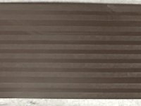
The image below shows the tracks on a LINCtape. You can see the slightly larger gap between the Mark and Data tracks. With higher magnification you can see some 0->0 or 1->1 on the Mark track. We will try to find a microscope with an attached camera so we can get pictures of the bits on the tracks.

LINCtape_Tracks.jpg
 
We are still slogging through the TU56/TC12 problems. It looks like the office environment where we have the RICM Lab, is electrically noisy. We see a strong 15MHz pulse every 4uS on the tape head data triax going between the TU56 and the TC12. Periodically this pulse will align with the zero crossing of the Data 3 tape head signal and causes the G882 to emit extra pluses. After some extensive investigating we found that the shield on the TC12 end of the Data 3 triax was not grounded. The PDP-12 TC12 schematics list this pin as F06T2, and it is really F06L2. The backplane has a Wire-Wrap from ground to F06T2 that does nothing. We added a wire, blue of course, from the ground bus to F06L2 to ground the shield of the Data 3 triax. Since this system was always run in an electrically quiet environment, it worked OK with the missing shield ground.

Our system was built in late 1973. I found the error on the 1969 prints, so maybe all PDP-12s have this error.
I didn't find a card in the back of the PDP-12 schematics so I can send this error to DEC.
 
"We see a strong 15MHz pulse every 4uS"

Do you mean a 15MHz burst every 4uS or a single much shorter blip?
Not that it makes any difference to your findings of course, just wondering what might be causing the RF.
 
Nice sleuthing!
And so ...?

It might be possible that all PDP-12s have this error. There are three more in the neighborhood, so I will have to check.

Our PDP-12 still doesn't boot OS/8 or LAPS-DIAL.

Next week we will format a tape and see if the drive and controller work OK. If they do, then we still have a head alignment issue.
 
The TC12 controller passed all diagnostics, but we didn't try the tape data test.

During a tape format it writes the Timing and Mark tracks on the first pass, I believe that it writes the reverse block numbers and CRCs on the second pass. On the second pass it sometimes stops the tape for a second and then starts again. We have no idea why.

We cleaned one of the tapes we were using, and noticed a vibration on the tape when it is moving. My TU56 at home does the same thing. Is this normal for a TU56?
 
I don't think it's normal, the tape should run quite steadily. Mine does. Does it do the same both sides?

I don't think I've seen the tape pause mid-pass during a format, can't honestly remember as its not something you need to do often, though I'm using a TD8/e anyway.

When I first refurbed my TU56 I had a similar vibration problem on one side with the tape sometimes seeming to 'flutter' over the head. One of the suggestions I received was to check the tape path alignment carefully and check the head and guides for wear. In the end it turned out that the oil-bearing bushes where the motor spindle comes through the panel were dried out and a bit sticky which was causing slight juddering. I don't know if you can get them but all I did was clean them up then heat and cool in oil to try to reimpregnate them. Don't know if this worked, but the drive ended up working OK.
 
Several months ago I cleaned and lubricated the brake bushings on my drive.

Both drives on the PDP-12 and both drives on my PDP-8/e have the vibration. Of course all four drives could have a problem.

If you lightly press a cotton swap on the tape between the guide and head, or between the guide and the reel, and move the tape you can feel the vibration.
 
Hmmm- the only other thing I can think of is that you do get various resonances as the tape spools which vary a bit as the spool sizes change. Mentioned in the TU56 manual. Could this be what you're seeing?
 
Back
Top