• Please review our updated Terms and Rules here

RK05 disk emulator development and discussion

Thanks George for all your work on this wonderful project. The new boards look fantastic.
I like the 0.1" headers which replace the inter-board FPC connection.
Did you keep the servo motor for the microSD adapter or is the adapter now static?
I am looking forward to see more about this.
 
Thanks, Tom and Paul.

The FPC connectors are quite small and inexpensive, but as we discovered while testing, they are also somewhat fragile. The 0.1" headers will be more robust which could be a benefit for a device that users might disassemble and reassemble.

The servo motor has been removed, for now, so the microSD mounting pedestal is much more solid. I really really really like the idea of inserting a card and having the "disk pack" move away from the user's view, like the real RK05. However, there were multiple mechanical issues and it just didn't feel robust. All of the electrical support is still present to have a motor again, someday. There's even a high-resolution PWM generator in the FPGA that produces much finer steps than the Pico programmable GPIO that was initially used. In this upcoming version, the servo motor and 3-pin header have been removed from the parts list.
 
It's a very impressive effort, I'm just watching from the sidelines but following the project with interest.

I don't know if this would figure but would it be possible to have a blank pad or via added near each LED and switch?
I could foresee a replica of the full size 19" wide 10-1/2" high RK05 front as a spinoff project in itself. Smoked perspex door, handle, screenprinted fascia, 3D-printed rockers, that sort of thing.
Something that follows the 'six foot rule' ie. it looks near indistinguishable from a real RK05 from 6 feet away.
The mini-front panel would sit behind it, and wires drawn out from it to the large panel switches and lights.
This is definitely possible. There are already pads for the switch wires and LEDs could be removed to expose rather large SMT pads. In a future version of the board it would be possible to add through-hole pads next to the LEDs... there's a lot of extra space in that area.
The rocker switches are already off-the-shelf switches but rocker handles that are more true to the original could be printed.
To move or lock the door, there's a PWM output with a duty factor that represents the desired position of the door. That could be changed to just a simple open/closed logic signal.
 
have you decided on a kit price?
I plan to ask just my cost for parts plus whatever amount for shipping. Rather than try to make a profit, I think the fun is to have some of these in use.
Plus, when configured as a tester, maybe we can enable the restoration of some real RK05 or Diablo drives.

It turned out to be more expensive than I originally imagined. The emulator/tester by itself has ~$82 parts cost. Cables, terminator, power supply, etc. can also be available.

Here's the BOM with material cost for emulator/tester plus accessories.
 

Attachments

  • RK05 emulator bill of materials v1 simplified v03b - BOM Sheet.pdf
    481.7 KB · Views: 11
  • RK05 emulator bill of materials v1 simplified v03b - Cost by Quantity sheet.pdf
    445.3 KB · Views: 11
Exciting stuff!
Definitely interested in a kit
(or, at the least, the schematics and VHDL to assemble my own)
 
George,

One suggestion for your emulator.

I don't know if you have any delays in your code to more accurately emulate the RK05.

I was thinking that if there is a version of the firmware that runs as fast as the RK05 interface allows, this could be used as the swap drive for TSS/8. There is a version of TSS/8 that was modified to use the RK05 as the swap device (with an expected reduction in swap speed). If your emulator can run at full speed it might emulate a DF-32 as closely as the TSS/8 RK05 swap driver will allow.
 
The present version has the exact same rotational latency as the RK05. This is necessary because the RK05 bus has index and sector pulses and binary sector address signals and the emulator needs to generate those so the controller can react properly.

However, the track to track seek time of the emulator is currently zero. In a later version I was planning to add an an attribute in the header to enable actual RK05 seek delays. It didn’t seem possible to calculate seek time based on the RK05 schematic alone because there’s an electromechanical interaction.

I’d like to have someone with a working RK05 collect data of track seek distance vs seek time. I think this is the pulse width of RK05_FILE_RDY_L following the seek command pulse on RK05_STROBE_L. I suspect this time may vary a bit from drive to drive. By knowing this function of delta-cylinder vs seek time the FPGA could create the same seek delay. But for now, it seeks really fast.
 
If the sector and track indexes arrived too quickly then the controller would get confused I presume. It would still be faster than a standard RK05.

On of the biggest issue in replacing the DF32/RP08 with the RK05 is that the fix head hard disks are byte addressable and can read/write from 0 to 4095 words in a single operation. TSS/8 takes advantage of that so the RK05 swap driver has to simulate that. This makes is slow from the PDP-8 end. It would be an interesting test to compare a real RK05 vs your emulator at the TSS/8 swap drive.
 
I’d like to have someone with a working RK05 collect data of track seek distance vs seek time. I think this is the pulse width of RK05_FILE_RDY_L following the seek command pulse on RK05_STROBE_L. I suspect this time may vary a bit from drive to drive.
RK5-2.png

This table is from p.10 of EK-RK5JF-MM-001. I'd suggest allowing up to 100ms for 200 (400 RK05F) track seek. The 'adjacent track seek' time of 0 ms. is incorrect. Earlier versions of the manual have it at 10ms which is about right. I'd expect the RK05F adjacent track seek time to be less than 10ms.
Does your emulator have the ability to act like an RK05F?
Does anyone recall if there was any software that made use of the 6 (or 12) spare tracks?
 
This table is from p.10 of EK-RK5JF-MM-001. I'd suggest allowing up to 100ms for 200 (400 RK05F) track seek. The 'adjacent track seek' time of 0 ms. is incorrect. Earlier versions of the manual have it at 10ms which is about right. I'd expect the RK05F adjacent track seek time to be less than 10ms.
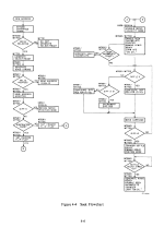
Thanks for the reference. I was looking to be more precise about the delay. Basically emulating the functions in this chart in the Nov 1976 Maintenance Manual (mostly the right side of the diagram)
1710400424148.png
When the track is close by the delay is essentially zero, as you mentioned. There's actually a test in the RK8-E maindec that tests this adjacent track seek delay. The early versions of the emulator FPGA code produced a delay slightly larger than zero, and it failed that maindec test.

The drive has a set of SN7483 adders that determine the difference between the present and next cylinder and enable low or high velocity modes depending on the distance needed to travel. I'm looking to generate a delay that's a function of this difference between present and next cylinder, and expecting that it's probably not a linear function.

BTW, I mentioned the wrong signal in the previous post. It's RK05_RWS_READY_L or BUS_RWS_READY_L that indicates when the seek is complete.

Does your emulator have the ability to act like an RK05F?
Planning to do this in a later revision. All of the hardware is present to operate as two platters with adjacent drive addresses and the software is configured to produce the 0/1, 2/3 etc. in the display. The RK05F mode would be enabled with just a software and FPGA update.
 
Back
Top