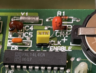
• Please review our updated Terms and Rules here

RTC Clock setting on Heath/Zenith Z-148 PC

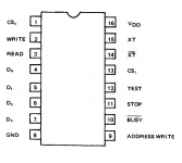
So here's what I'm getting, all pins with the yellow jumper installed.
1 = H ------- 16 = H
2 = H ------- 15 = Squark ! (internal oscillator)
3 = H ------- 14 = Squark ! (internal oscillator)
4 = H ------- 13 = H
5 = H ------- 12 = L
6 = H ------- 11 = L
7 = H ------- 10 = 1HZ
8 = L ------- 09 = H
1669470846459.png
I also tried with the yellow jumper removed,
1 = H ------- 16 = H
2 = L ------- 15 = Squark ! (internal oscillator XT)
3 = L ------- 14 = Squark ! (internal oscillator XT)
4 = L ------- 13 = H
5 = L ------- 12 = H
6 = L ------- 11 = H
7 = H ------- 10 = 1HZ
8 = L ------- 09 = L

is my probe/ear not fast enough to catch the pulse ?
I'm using the "mem" setting on the logic probe to try and catch a pulse as a light.

The only ports doing anything vaguely interesting (not reading 255) are port 888(378h), 976(3D0h) and 1024 (400h) which appears to be counting up 0 to 255, repeatedly.
 

Attachments

  • MSM58321RS.pdf
    1.4 MB · Views: 3
Since I don't own your logic probe, that's hard to say.

The other possibility is that the RTC is memory-mapped; not common, but it happens. You might try decreasing the granularity in your probing to 4 instead of 8. Otherwise, I'm out of ideas at this point.
 
logic probe claims to be sensitive to 25 ns (20mhz) pulse width.

but how does this sound:
the range of ports 616 (268h) to 623 (8 ports) all read 247 with jumper in, all read 255 without the jumper!
nothing else changes 100h to 400h step every 4.

1669491398422.png

now this next bit is my poor understanding :-
so now at address 268h, I think we are knocking on the door, but we don't know the keycode - it needs a value on the 4 bit address line to make it do anything ? "0101"

How I think it works : I have to send Out (portAddr, value), and then read the set of ports and decrypt the values.
 
You may have something there. Certainly worth a try. As I said, it's impossible to know what's in that PAL. Seeing where the traces go (particularly pins 14-17) might shine some light on what it's supposed to do. After all, the PAL is purely combinatorial.
 
I'm making slow progress -

when I output (basic) say,

OUT 616, x (x = 0 to 15)

the address lines change on the clock chip and my logic probe goes from high to low on pins 4, 5, 6, and 7, (4 bits)
the state changes high to low with the bits on the 4 bit address bus ! I can read the bus in binary !

so this i/o port 616 decimal, 268h is definitely the address of my clock.

now what ? where does the data come out ? same port ?
 
Last edited:
Pay attention to pin 9 of the RTC chip. It's the "ADDRESS WRITE" pin.
Basically, you latch an address by placing the 4 bit register address and asserting ADDRESS WRITE. Then, you can read or write any one of the 16 registers by asserting READ or WRITE.
The question becomes how is ADDRESS WRITE asserted? If this were my design, I'd use one of the upper 4 bits to signify that an address is being written. But this isn't my design--just saying that great minds think alike....
 
I traced pin 9 to one of the 74LSxxx chips, that doesnt tell me much.

Pushing values 0 to 15 onto the 4 bit data bus changes the INP values in ports 616 to 623 to be “255-x”,
0 out gives 255 INP,
1 out gives 254 INP,
..
15 out gives 240 INP, etc. Basically FF to F0.

To get the latch pin 9 to work, i could try output on port 616 , 0 to 255 with logic probe on pin 9 to see if any value changes the state of pin 9.

Could the latch be controlled by another port ?
 
Dunno--I do see an LS173 and an LS174 there--the 173 is a 4-bit latch; the 174 is a 6 bit latch. You may have to trace the connections around the RTC and come up with a schematic to get the whole picture. The 368 is just a hex bus driver--and we already know what outputs the PAL14L4 are.
 
More Success I can now flip the pin 9 ADDRESS WRITE ! low to high
you do this by outputting on any ports 608 through 615.

OUT 608,255 : turns it on (High, 1111,1111), also flips the state of pins 2(WRITE) and 3(READ) both to High
OUT 608,0 :turns it off (Low, 0000,0000), Pins 2,3,9 all go low

lets see if intermediate values change the state of write and read, your upper 4 bits might be the charm... F0 vs 0F ?

now,
1) do I put a number "0000" on the 4 bit bus with port 616, then set the ADDRESS WRITE = HIGH with ports 608 to 615 ?
2) do I set the ADRESS WRITE = HIGH first, then try and push "0000" onto the 4 bit address lines?
or 3) can It all be done in one operation? i.e. OUT 608, 240 = F0 = 1111, 0000

0000 should give us a value for seconds....
perhaps READ and WRITE shouldn't both be high.
 
I don't know about cracking it but I've got tinitus from my logic probe now...

any bets on what OUT 608,128 (Binary 10000000) will produce - pin 9 high, but no read and write ?
 
Well, look at the pins when you do out 10000000 01000000 00100000 00010000 (80h, 40h, 20h, 10h).
If the upper 4 bits manipulate the WRITE ADDRESS, READ and WRITE pins, that should say something.
On the other hand, it could be that things are really atomic. One OUT to set the operation bit, then an IN or OUT on a separate address.

My guess is that the RTC chip is a re-worked watch chip, so probably not very fast.

PS: I wish my continuity tester was loud enough to make my ears ring.... :)
 
more progress, outputting a value of 237 = EDh =(11101101) or 236 = ECh = (11101100) on ports 608 to 615 gives,
ADDRESS WRITE = H
WRITE = L
READ = H
on the address pins 4,5,6,7 we have L,L,L,L = 0000

similarly, outputting 235 = EBh= (11101011) or 234 = EAh= (11101010) to the same ports gives,
ADDRESS WRITE = H
WRITE = H
READ = L
similarly on the address pins this gives 0000

so probably atomic...
 
Last edited:
After a couple of evenings manually pushing 4 bit binary on and off the bus I had a breakthrough:
Stop trying to read the clock, first you must write to the clock!
I pushed 0000 to all 12 registers. Effectively zeroing out the clock to 00:00:00 on 1-1-1980.
Then I tried reading the s0 register again and I got a value counting down from 255 to 246!
Subtracting this from 255 gives me a count, 0-9, that increments each second….
I think I’ve got seconds and similarly I see 10’s of seconds for the S1 register.

I’m so close to cracking this by brute force rather than careful logic.
I’d like to say I understand how bits are getting from the isa bus to the clock chip…I’d like to say that….

Somewhere all the output bits are flipped, hence the need to subtract from 255.

Tomorrow I’m going to try and read minutes…
 
Ok so after a few wrong turns it seems like I’m able to set and read the clock using decimal ports 615 and 616.
I set the date and time earlier. Switched off the machine. Came back after an hour and cold booted. The date was still correct but the time was reset.
I still need to deal with 24 hr clock/12 hr and leap year bits.
 
Yes, so far everything has been done in GWBASIC.
Will TIME$ let me sync the hardware clock with the system clock ?

Can you recommend an assembler program ? I”ve been putting off learning “machine code” since the 80’s.
 
One program that might be of interest at this point is MMCLK.SYS. It comes with assembly language source:

http://annex.retroarchive.org/cdrom/640_studio_iv/UTILITY/MMCLK12.ZIP

You can look into it without having to download everything, here:

http://annex.retroarchive.org/cdrom/640_studio_iv/UTILITY/MMCLK12/index.html

According to the docs, details for writing a CLOCK$ type device driver are included for anyone interested in writing such a driver for a different clock card.

Another program, written in C, may also be of use:

https://minuszerodegrees.net/rtc/dtk/dtkclk11.zip
--- OR ---
http://annex.retroarchive.org/cdrom/640_studio_iv/UTILITY/DTKCLK11.ZIP

Again, you can look into it without having to download:

http://annex.retroarchive.org/cdrom/640_studio_iv/UTILITY/DTKCLK11/index.html

Neither of them are for programming a MSM58321 RTC chip, but both were written by the same person.
 
I think I’ve done it ! (All in gwbasic) - the 24/12 hour bit D3 means you have to add 8 to the hours 10’s value when you set it. Then subtract it off when reading that register.

22F6770F-A914-4B0A-9713-FFA7D588B0A5.jpeg

I was able to set the hardware clock, read it back.
Then used the values from the hardware clock to update the system clock, time$=“xx:yy” and date$=“mm-dd-yyyy”. Still gwbasic.

Exit to dos and the time and date functions work. Until the next reboot.

After a couple of hours and a cold boot and the hardware clock is still keeping time. If the date and time are still correct tomorrow then I’m going to declare victory.

It looks like Ive still got quite some learning to do to turn my gbasic proram into a driver.
 
Back
Top