• Please review our updated Terms and Rules here

Ruud's diagnostic ROM for IBM PC, XT and compatibles

I am looking forward to a ROM based diagnostic that is not misleading when it comes to the testing of conventional RAM.
Please, explain a bit more? I check the very first 2 KB of RAM very thoroughly (I think). Having a reliable base where I can create a stack I use the same subroutine toy check the rest of the memory. So if you think my test is not good enough or you have other complaints, please tell me! I'm looking forward to ideas that can improve the tool. We will all benefit from it.
No complaint/criticism. The 16K CRITICAL MEMORY REGION test in the Supersoft ROM diagnostics is many times misleading. One example of many is the screenshot that you pointed to in post #12. Notice that with no RAM fitted, the Supersoft diagnostics do not fail bit 0.

I am hoping that you will do a much better job of reporting problems in the first 16K of RAM.
 
No complaint/criticism.
I didn't see it as complaint. And criticism can be good. But not being a native English speaker does sometimes give me trouble to understand what someone exactly means. And the other way around is quite possible as well.

The 16K CRITICAL MEMORY REGION test in the Supersoft ROM diagnostics is many times misleading.
To be honest, I have no idea at all why Supersoft does give the very first 16 KB this name. OK, a 5150 with a 16-64KB board won't start at all if the first 16 KB are bad. But this ROM is meant for the 640KB board as well and that one needs 41256 DRAMs in the first row. And then this "16K CRITICAL MEMORY REGION" doesn't make any sense anymore. For me a good working 2 KB of RAM at the start is good enough to complete the test.

Notice that with no RAM fitted, the Supersoft diagnostics do not fail bit 0.
I noticed that too but I considered that as bug. In quite some cases I studied the source code of the Landmark ROM to find out how they did things. I'm quite sure that I know how to test RAM and therefore I didn't even had a look at their routines and used my own ones.

I am hoping that you will do a much better job of reporting problems in the first 16K of RAM.
Do you have something in mind? Then please tell me, I'm always open for nice ideas.
My philosophy is simple: test the RAM byte by byte and stop at the first error. The line with "Checked RAM" tells you how many KBs tested fine. The next two lines show you which bits are bad. If there is only 64 KB on board than the line with "Checked RAM" will show 64 KB as amount of tested RAM and (normally) all bits will be bad. If you have two banks of 64 KB and you have one or two bad bits, then you know one or two bad RAMs in the second bank (or badly seated or corroded connections). Up to three bad bits I notify as "bad RAMs". If more than three bits are bad, I'm not sure what to think of it and I signal "End of RAM".
Please note that I don't display the exact address of the error. The screenshot shows 06E40 as bad address. (if there is no RAM present, how can the counter get so far, even beyond the 16 KB boundary ???) The user now must have some knowledge of hexadecimal numbers and must now calculate the number of good KBs. Then he knows in what bank to find the trouble shooter. I simply give the right KB, in this case 27 KB. And the user knows immediately that the troubleshooter is in the 2nd bank in case of 4116 DRAMs. In any other case it is always the first bank.
 
Do you have something in mind? Then please tell me, I'm always open for nice ideas.
I agree with what you are doing.

First: it it the very first public version and never tested in a real PC, just the PCem emulator. But I appreciate it very very much that you actually tested it in a real motherboard :)
I will (when time permits) do some testing on real hardware as well.
 
Hi Ruud,

same board, next try:

https://imgur.com/a/U2wSLtX

Exchanged the RAMs and switched randomly some DIPs.

You cannot see in the picture, but the cursor is again in the top left of the screen and nothing is happening...

What does it mean?

To my surprise, currently the Supersoft ROM is not outputting anything...no picture, no beep! That a big plus for your ROM :)
 
OK, I promised to test my diagnostic ROM on real hardware. Saturday morning I got a migraine attack. Fortunately my headaches are minor compared with other people that I know that have migraine but still.

Late in the afternoon I disassembled the motherboard, replaced the VGA card with a MDA one, started the PC and.... nothing on the screen. To make a long story short: the first 1 KB of RAM on the MDA card was broken and a faulty switch in the MDA monitor.
Sunday I was able to test the ROM itself. I ran into two weird errors:
- Like when testing it on PCem, timer 2 of the 8253 failed. I use a subroutine to test all three the timers (just like Landmark does) so I was quite puzzled. I had isolated the part in Landmark that does test the 8253, copied that to my source, killed my own part, assembled the whole, started the ROM and..... timer 2 failed here as well ?!?!?! The only ide a I have right now is that I do something before the test that for one or another reason influences the test for timer 2.
- My keyboard was bad according my ROM. OK, I use a KVM switch + AT2XT converter but if the PC doesn't complain, why should my ROM? But being a good sport, I installed an original Taiwanese XT keyboard and... error as well. And here I have no idea at all what is causing this behavior. Back to the drawing board.

To be continued....
 
- Like when testing it on PCem, timer 2 of the 8253 failed. I use a subroutine to test all three the timers (just like Landmark does) so I was quite puzzled. I had isolated the part in Landmark that does test the 8253, copied that to my source, killed my own part, assembled the whole, started the ROM and..... timer 2 failed here as well ?!?!?! The only ide a I have right now is that I do something before the test that for one or another reason influences the test for timer 2.

I see you copied the description of port 61h from Ralf Brown's PORTS.LST, where bit 0 is misleadingly described as "gate to speaker". This is actually the timer 2 gate input on the 8253, when disabled that timer doesn't run at all (the speaker can then be controlled directly by bit 1). To leave the speaker off but enable the timer, you should always write xxxxxx01 to that port.
 
Last edited:
Hallo dreNorteR,

I just checked a schematic and you are absolutely right! I will change my code ASAP and I will you all know.
Many thanks!
 
Ah, found in the sources
Code:
;**  Output a debug code to the two main LPT ports and IBM's debug port
%macro OutDebug 1
	mov	al,%1
	out	80h,al			; IBM's debug port
	
	mov	dx,278h			; LPT 2
	out	dx,al

	inc	dh
	out	dx,al			; LPT 3
%endmacro
 
A reminder that on PC-class and XT-class machines, not all POST cards will be able to see codes sent to port 80h.
See post #5 at [here].

I am not saying that it is pointless to send codes to port 80h. But I think that users should be warned, in documentation, that a modern POST card may not show port 80h codes on PC-class and XT-class machines.
 
modem7 Thank you! My post card is exactly the same and does not work nor with Ruud's BIOS nor in DEBUG (O 80 AA).
Never tried it in XT before... (going to basement to search for LPT port)...
 
The other thing that needs to be done for the IBM PC and IBM XT, is that, past the point where the DMA controller has been set up to do RAM refresh, the DMA controller then has to be disabled before sending a diagnostic code to port 80h.

Example:

Code:
B0 04   MOV AL,4
E6 08   OUT 8,AL      ; disable DMA controller
BO 03   MOV AL,3
E6 80   OUT 80H,AL    ; send 03 to POST card
F4      HLT           ; halt
 
Port 80h is a DMA0 ''page" or "segment" register implemented in 74LS670 (since i8237A can't cross 64K boundary).
DMA0 is used for refresh RAM (reading any sequential addresses) so it should be safe to write any value to the port 80h.
 
Port 80h is a DMA0 ''page" or "segment" register implemented in 74LS670 (since i8237A can't cross 64K boundary).
DMA0 is used for refresh RAM (reading any sequential addresses) so it should be safe to write any value to the port 80h.
I did not mean to imply that it is unsafe.

* Prior to the point where the DMA controller has been set up to do RAM refresh: Simply sending a byte to port 80h works; it appears on a vintage POST card.

* After to the point where the DMA controller has been set up to do RAM refresh: Simply sending a byte to port 80h does not work; to have bytes appear on a vintage POST card, the DMA controller has to be disabled first.
 
It seems there is another issue with port 80h, XT and new POST card. AFAIK new POST cards work in the Slot8 on the original IBM PC XT 5160 motherboard. Slot8 is an internal motherboard bus to access a I/O ports in the range 000h-0FFh. Port 80 fits to this range. Also new POST cards have no AEN pin (A11) necessary for correct decoding. Slot8 is an unique feature of the IBM XT 5160 motherboard, all another compatible motherboards have Slot8 parallel to the Slot1..7.
 
A reminder that on PC-class and XT-class machines, not all POST cards will be able to see codes sent to port 80h....
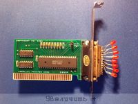
Funny, just received this card some days ago, haven't even tested it yet. It only costed $4 so no harm done if it cannot be used in XTs. I have a self built one anyway, one with dip switches to choose the IO address. And for the people that don't have such a diagnostic card at all, that's why I added the LPT ports.

After to the point where the DMA controller has been set up to do RAM refresh: Simply sending a byte to port 80h does not work; to have bytes appear on a vintage POST card, the DMA controller has to be disabled first.
I use port 80h for ages and never ran into trouble (AFAIK). But that is the advantage of having the source code: "You don't like it? Then change it!" :)
 
Just an update: still busy but due to personal circumstances I have less time than I wanted.
 
OK, I solved the keyboard problem. I ran into three problems:
- a cat: during the debug session I was called by my wife. When coming back I noticed one of the cats standing on my desk. I compiled my file (I just finished editing), put the EEPROM in the socket, started the PC and it stopped before reaching the keyboard test. ????? OK, just undo the last changes and try again. That's how I noticed that the cat had managed in some way to delete whole lines of the program. Untrusty creatures, just out to sabotage your work behind your back :)
- a missing STI. Without it there won't be any keyboard interrupt detected at all. But why worked it fine under the PCem emulator then? My only conclusion: another bug of this emulator.
- after finding the missing STI it still didn't work. A loop in the keyboard part, shortened by me to speed up the program, was the cause. And that worked fine under PCem as well.

I have to upload the sources yet, I'll let you know.
 
Back
Top