• Please review our updated Terms and Rules here

Ruud's diagnostic ROM for IBM PC, XT and compatibles

- a cat: during the debug session I was called by my wife. When coming back I noticed one of the cats standing on my desk. I compiled my file (I just finished editing), put the EEPROM in the socket, started the PC and it stopped before reaching the keyboard test. ????? OK, just undo the last changes and try again. That's how I noticed that the cat had managed in some way to delete whole lines of the program. Untrusty creatures, just out to sabotage your work behind your back :)
Many years ago, at work, an application test failure was discovered to be caused by a block of code that somehow went missing 'on my watch'. I claimed to my fellow workers that whilst I was getting a coffee, a fly must have landed on the Delete key. (I wasn't prepared to try the 'damn static electricity' excuse yet again.)
 
As mentioned as a note in the source code, I started to add beeping the the ROM. The idea was to output the debug code as binary code in the form of long and short beeps. Bad idea: not only were all those beeps driving me crazy but it delayed the whole diagnostic process. So I decided to output only a beep after outputting the first text to the screen so people know something must be seen now and when the CPU is halted due to a critical error.

But what about people people that don't have access to a CGA or MDA card and/or monitor and therefore rely on the beeps? Quite simple: I will add an assembly condition to the source code. Just switch it on to create a ROM that contains all those magnificent debug codes.

Any other ideas are welcome!
 
Hallo allemaal,

Again, as promised, you can download the binary and the source at http://www.baltissen.org/zip/diagrom.zip. It should work as intended but I'm going through everything again to see if I can improve things. As mentioned earlier, I added sound but this BIN will beep only at the beginning.

But I'm not satisfied with the way things are executed or tested. The main one is that screen is initialized first and then the CPU is tested. By the time you reach this part I don't expect to find a faulty CPU any more. Or it must be one which has a flaw that affects an instruction that hasn't been used so far, for example JPO or JPE. The same for testing the ROM itself: it should be done before any other action IMHO. Otherwise you run the risk of finding an error that isn't caused by the subject-under-test but by a faulty CPU or ROM.

So what I will do is to start with testing the CPU and the ROM itself. If these two are found to be fine, I initialize the screen and continue with the rest. If one of these is found to be bad, the diagnostic will halt. But how will you know what is the cause of the error? The most simple way is to look at the debug code at the LPT port or a card that can read port 80h. If you cannot read the code, then only the CPU, ROM or something else can be bad. The CPU and ROM can be tested in a working system. If both work fine with the working system, "something else" is to blame. And with "something else" I mean glue-logic, buffers, gates and other things that cannot be tested as so.

Another idea was skipping the test of the CPU and ROM in the next runs. But then it occurred to me parts can become faulty when warming up. So I decided to test them also in the other rounds. But this means displaying messages and I have to find a way to skip these messages without to much overhead for the original test routines.

To be continued.....
 
CPU test is very useful since there are alot of "fryed" CPUs (i.e. NEC V20) from China.
https://www.youtube.com/watch?v=L4WplIZ02cI
I obtain quite a lot of parts for my projects and repairing computers by scrapping boards using a gas torch. De-soldering ICs in the normal take up much too much time (unless it is a rare or valuable IC). Does the process destroy ICs? I don't think so. OK, occasionally I run into a broken IC. But quite some of the boards I scrap were broken on forehand so the IC could already have been bad before I de-soldered it.
 
Another idea was skipping the test of the CPU and ROM in the next runs. But then it occurred to me parts can become faulty when warming up. So I decided to test them also in the other rounds. But this means displaying messages and I have to find a way to skip these messages without to much overhead for the original test routines.
Skipping the messages during the first run proofed to be a bad idea. But the solution was quite simple in the end: I placed a copy of the two tests in front of the main loop.
 
A frying pan and peanut oil can be used to strip boards. It seem it is one of the oils that holds up to the temperature required.
Wear protective clothing and a face shield.
Dwight
 
Hallo allemaal,

You can now download the binary and the source at http://www.baltissen.org/zip/diagrom.zip. I consider it as finished. I would appreciate it if somebody could test it in an IBM-PC. I used a trick to find out if the ROM sits in a PC or a XT. It works fine in a XT clone but I was not able to test it in a PC. The only difference is that the screen will show two blocks with dip switches instead of one for the XT.

I have decided not to work on a diagnostic ROM for the AT. I have only one AT, it is a lot of work, the Landmark version seems to work fine and I have several other, IMHO, more interesting projects. I'm sorry if you had high hopes.

Comments, wishes and bug reports regarding the PC/XT version are welcome of course.

Have fun!
 
I'm trying to reapir XT clone motherboard but I have no CGA nor MDA cards. Will your test ROM work with (uninitialized) VGA ?
 
Will your test ROM work with (uninitialized) VGA ?
Unfortunately not. The hardware of VGA cards can differ and that's why the ROM is on the card: it contains the routines to initialize the card and the various INT 10h routines. And I'm sure that these routines use subroutines and that means that a stack, and therefore RAM, is needed. And RAM is not available during the first tests because the various ICs that make the dynamic RAM not to loose their data are being tested and thus unavailable.

During writing the above the idea rose to check for VGA once the RAM can be used. You should at least see a start-up message of the VGA card. (attention: not all cards do this but IMHO most do) But it seems to me that you don't see anything. That means either you have such a message-less card or that the CPU, 8237, 8253 and/or glue-logic is broken.

The source has a flag to enable the beeping at every stage. Or build/buy a tester for the LPT port or ISA bus. The one for the ISA bus is worth to buy.
 
I burned a ROM and ran the diagnostic code in a stock IBM 5150 PC. Attached is a photo of the output that is displayed on the screen. Thank you for making this project available to the forum! Michael

ruud_3.jpg
 
Attached is a photo of the output that is displayed on the screen.
First I thank you for your praise!

I would be interested in the right half of the screen because that part should show the settings of the TWO blocks of dip switches. First I want to know if two blocks are shown at all and second if the settings of the switches on the screen is the same as the real ones.
Many thanks in advance!
 
Hi dude.

I'm Leandro, from Brazil. I'll try your diag ROM in some brazilian XT clone dead motherboards. It would be a great tool if it works. I have some Juko motherboards too, but they work with almost a single chip like the Faraday FE2010A.

Do you think your ROM could work with these boards? Thank you.
 
The computer that I used to test the ROM had a Juko board. If the hardware is reasonably compatible, I don't see any reason why it should not work.
 
JUKO, Acer, Faraday and another 'chipset'-based XT boards are hard-to-reair... Memory tester is only useful feature or you have to replace a 'chipset'.
 
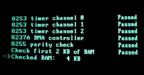
I was working with my Commodore PC20-III and suddenly thought of testing the diagnostic ROM here. What happened was quite strange:
- during all the runs Timer 1 failed.
- during all runs the ROM thinks it is dealing with a PC, thus showing two blocks with DIP switches. Left block: all switches up, right block: all down.
- during the first run it doesn't see any RAM at all except the very first 2 KB
- during the second run it sees 512 KB of RAM
- during the third run the test stops completely during testing Timer 0. I have no explanation for this behaviour for the moment.
 
Ruud JFYI: A VGA initialization sequence for OAK OTI077 and Trident 9000i (also known by Sergey Kiselev's 8-bit VGA)
It would be good to add it as optional module for diagnostic ROM.
https://habr.com/ru/post/406193/
(Article in Russian, use translate.google.com . Anyway C code is international :) )
 
And what if none of your VGA cards is of this type? The 8-bits cards I have are Trident 8900. And adding VGA support doesn't speak to me; what do I gain with it? I admit, all my desktops have a VGA card and AT2XT module so I can use them in combination with my KVM switch. But when repairing a board, I still use the good old MDA card.

But as said before, the sources are free. So feel free to add VGA support :)
 
I was working with my Commodore PC20-III and suddenly thought of testing the diagnostic ROM here. What happened was quite strange:

I'm not surprised; the P20-III is a clone that integrates many functions into a VLSI. I had to patch a recent project because I usually use OUT EE,AL as a bus delay mechanism that doesn't trash any registers, but it crashed the PC20-III -- turns out, EEh is where that system keeps some timer functions. (I changed it to IN AL,61 instead as I didn't need to preserve AL in that code block.)

In other words, don't worry if your diag rom doesn't work on drastically-different clones.
 
Back
Top