• Please review our updated Terms and Rules here

S-100 Power Supply Design Question

Hello Rich, yes I have a print for the open frame S-100 project (enclosed). It is based on the
older version of the S-100.com 8-slot motherboard. It should work for the 9-slot one with
adjustments. The card guides were purchased from Mouser (Bivar VG2-5). You don't need the
power-on delay relay setup but I like it as it prevents me from removing cards with power on and
it allows the supply to stabalize during turn-on (mainly for linear supplies-not so much for the
switchers).

>>> Charles


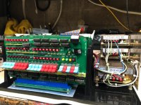
I got around to building this setup (converting from my CompuPro cage-on-plywood) and it's an excellent design that was pretty easy to build. My bottom frame was about 1/2" shorter so I had to adjust the offsets on each end to make up for it.

Overall, the diagram was very thorough and was easy to build from. Here are a few observations and suggestions:

* Multi-decimal measurements are very hard without a digital caliper since I didn't have a tenths-ruler. There was enough wiggle-room in the holes that any inaccuracy did not have much of an impact.

* Having the drill hole dimensions was helpful, but the intended screw size (4-40 or 5-M3) wasn't indicated.

* The mounting screw sizes on the bottom of the S-150 supply are 5-M3 and the sides are 3-M3. Since I didn't have metric screws, 4-40 worked, but when all you have is a hammer, everything looks like a nail as they say.

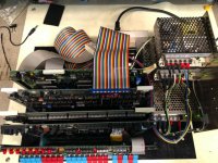
* My plastic board was shorter by about 1/2", so I mounted the power supply stack so that the sheet metal lined-up with the outside edge and I shifted the entire board stack to the left a little. I also moved the power supply stack further back to accommodate a small switch/LED panel I used on my other setup. If the plastic sheet has a paper protective layer, drawing this out is easy. Mine didn't have that (it's a satin black base). So, blue 3M painter's tape, a center punch, and a Sharpie worked well for this purpose.

* I would recommend mounting the middle power supply 1/2" forward of the current dimension so that you can wire-up the supplies when mounted to the metal (I built it as a sub-assembly). If they're mounted in-line, you can't get to the screws.

* I did not use fuses, although I drilled the holes for the holders. These supplies have short circuit protection which of course doesn't necessarily protect the traces. I've never had an issue, but I can add them later. I was looking into self-resetting fuses for it...the new revisions of the backplane have that, but the older ones have an error in which the PTCs protect the LEDs and not the slots. Those LEDs are expensive you know :)

* I'm a little concerned about the accumulation of static on the plastic; not sure how to deal with that, but I guess the cage of the power supply "connects" to the base through the mounting screws. I punched some card stock and put it under the backplane for good measure. I did not use copper tape or anything.

* For power input, I have an "input block" which has a switch, IEC connector, fuse and line filter in a single package. I mounted it in a piece of wood which I then mounted on the board behind and inset to the power supplies so that the 0.25" terminals clear the S-150 supply. I did not build the relay part of the setup.

All I'm waiting for at this point is a new spool of black 16AWG wire I ordered, and then I can finish wiring the supplies to the backplane.

Thanks again for a great design and sharing it with the list!

Rich
 
Hello Rich, glad the S100 Open Frame drawing was useful. The multi-decimal measurements are a
product of AutoCAD as I don't think the version I use has fractional dimensions. Mostly using a
1:10 scale with 1 decimal accuracy is sufficient for assembly. The staggering of the power
supplies is a good idea as you are correct, it would make wiring easier. Fuses are a force of
habit, the supplies have auto short circuit protection so are not necessary. I haven't noticed
any static buildup on my setup as the plastic is grounded by the supply as you indicated. In any
event, thank you for the feedback it always helps to get another viewpoint to improve a design.

>>> Charles
 
I really appreciate you putting the drawing together. It was very easy to work from, and I agree, if I had a 1:10 engineering ruler, it would have made it a tad easier. Really what's important is the measurements around the backplane. It was the design that I was looking for. If you saw the nonsense I did with pieces of wood with routed slits, you'd chuckle.

Have a great weekend Charles.

Rich
 
S-100 Power Supply Design Question

Here are a few pictures from my setup (which, essentially, is a CompuPro ZPU setup). Works great.

Just curious if you considered cooling at all. In some of my previous plywood-based hacks, I had two 80mm fans on the left side of the cage (they're left over from old DEC MC200 serial concentrators). I'm a little leery about relying solely on convective cooling for basically 40-year-old boards (other than the mini front panel).

Thoughts?

Rich
 

Attachments

  • IMG_1856.jpeg
    IMG_1856.jpeg
    118.3 KB · Views: 1
  • IMG_1857.jpeg
    IMG_1857.jpeg
    128.9 KB · Views: 1
Hello Rich, I like the way your system turned out. The power supply stack worked out very well. As to heat concerns, I use my open
frame unit for de-bugging boards and times when I just want to tinker so it is not my main S100 system. If it was the main or only
S100 unit I had, I would consider cooling fans. As it is, most of the S100 cards I own have good heat regulator design S/T you can
hold your fingers on the regulator during operation without getting burned. For the few very high current video boards I have, I
started using CUI (V7805-2000R) switchers which generate no heat at all, so unless enclosed, heat build up from regulators has not
been a problem for me. In any case, cooler is always better so a fan would not be a bad idea at all.
Also, good job on the mini-IMSAI front panel card.

>>> Charles
 
Thanks very much. It was a great project to do.

I have several S100 crates, but they all have something in them -- an 8800b, an IMSAI, a TEI 22-slot with a Seattle Gazelle and a TEI 12-slot with a "new" system based on cards from S100Computers. This one is, like yours, a "random testing" bed...except right now it's basically a fully functioning CompuPro ZPU (Cromemco CPU, CompuPro RAM17, CompuPro Disk 1, front panel, and CompuPro System Support Board) that runs CP/M 2.2 on 8" drives.

I have not actively replaced any of the regulators with switching equivalent. On "new" boards, I use 3A regulators from Pololu. I'll see if I can incorporate fans without making it look ugly.

Rich
 
Once again, thank you all for your input. I took on this project for its educational value; I have learned a lot already*. The backplane is constructed, the power supply passes initial tests, the chassis is being modified to accommodate the various elements and now I have come across another question I would like to ask:

The backplane and cards will be consumers of the output of the three Meanwell switching supplies, nominally +/- 16VDC and +8VDC. The chassis will also have a need for +12VDC for fans and for any (future) drives and +5VDC for drive logic. Would it be better (in the sense of advisability) to add a fourth power supply with these 5/12 voltages as standard output or to derive these voltages from the existing supplies? Either approach is feasible; I am just wondering which is more sensible.

Thank you for your responses.

-CH-

*
- You can substitute a Hakko heating element in your Zeny soldering station iron but the Hakko puts out significantly more heat. Optimum soldering temp is about 70 C. lower according to the display.
The Zeny's display will need recalibration but for now I just dial down the heat.
- The "power entry module" - Schaffner FN9260-10-06 - had, in addition to an L-C filter circuit, two 5x20mm fuses. Who knew? Not me, until I looked up the datasheet on line, but it simplified the design of the AC power control.
- The Meanwell RSP-75 lit right up when power was applied but the two LRS-150s did not, until I saw the note and found the internal switch and set them from 230 AC to 115.
 
Good question. I think it would be too hard, and probably not too efficient, to further regulate these voltages down for use with a floppy drive. I happen to have a 45W switcher that was scrapped from some PC-like thing and it has the right voltages (and connector) for a floppy. I would consider finding a small dual-voltage switcher on the surplus market and use that. Of course you can use any XT/AT/ATX supply that you may have, but those are overkill for a single floppy and may not regulate properly if the load isn't great enough.

Rich
 
... I think it would be too hard, and probably not too efficient, to further regulate these voltages down for use with a floppy drive.
Rich

Thanks, Rich; makes sense to me. There is plenty of room in this chassis so one more switcher is pretty easily accomplished. And thanks, too, for maintaining classiccmp.org which has been very useful to me as well as many others, I'm sure.

-CH-
 
Thanks, Rich; makes sense to me. There is plenty of room in this chassis so one more switcher is pretty easily accomplished. And thanks, too, for maintaining classiccmp.org which has been very useful to me as well as many others, I'm sure.

-CH-

Glad to help. I used to hunt for surplus switchers at BG Micro, MPJA, or All Electronics.
 
I dug through the drawers and found a 12VDC 3A switcher that will do for now, mainly just to run the fans.

The case I chose - CoolerMaster HAF XB - is roomy enough for me to run the PSUs side-by-side instead of stacked. I think I'll get better airflow around them and, attached to an aluminum base plate, sort of a heat sink as well. Plus the plate lifts out with everything attached if need arises. The chassis is exceptionally deep; there is an additional 7 inches above the "mezzanine" rails, on which I will mount the backplane, cards and cage.

Pics attached.

-CH-

PSU_Array1.jpg PSU_Array2.jpg PSU_Array3.jpg PSU_Array4.jpg
 
Last edited:
Never seen an Altair, or an IMSAI, either, for that matter. I considered finding a "legacy" machine but I thought better. Not so much for the cost, as this project will probably equal that, but for the educational value and because I thought it better to start with new components - some old ones are becoming unobtainium - and because I didn't want to commit the mortal sin of sending a classic to an early grave.

-CH-
 
An additional question has arisen: How to specify (name, locate, purchase) the "lifting levers" that sit at the upper corners of a 5x10" S-100 card? I'm building a cage but will need to know how high the top lip should be.

Thanks for the info.

-CH-
 
Thank you. Also available at Newark. Datasheet suggests top of cage be same height as top of card. QED.

-CH-

The ejector tab is the same hight as the board edge. But cards are not the same size. Mine vary by almost 1/10 in. I picked the shortest card I have and made the cage hight 1/16 inch shorter. Want to be sure the cards bottom out in the connector and not on the guides.

joe
 
The ejector tab is the same hight as the board edge. But cards are not the same size. Mine vary by almost 1/10 in. I picked the shortest card I have and made the cage hight 1/16 inch shorter. Want to be sure the cards bottom out in the connector and not on the guides.

joe

It would then depend on the offset of the hole at the corner of the board. You'd want the hole to be such that the ejector does not restrict sufficient travel of the board in the connector.
Still, the connector doesn't make the connection, to the board, at the bottom of the connector. Look at the board and note where the wiping mark is for your particular connector. As long as it is inserted far enough to be about 0.10 inch beyond the wiping mark, it will be enough to work. Bottoming of the connector is not needed. In fact having it not bottom out will help from having connectors broken by forceful insertions.
Dwight
 
Thanks, gents, for your responses. The ejectors I ordered from Newark haven't arrived yet so a test fit isn't possible, but the cage (walnut) isn't fully assembled, either, so I may have some wiggle room. If I manage to break a connector through forceful insertion I will be quite surprised. Not looking forward to replacing one, but I do have a spare.

This has been a learning project and as such has taken a number of new directions already. Two steps forward, etc. I'll report back when I get it sorted.

Thanks again,

-CH-
 
Back
Top