• Please review our updated Terms and Rules here

S-Video to EGA/CGA Adapter options

VirusVox

Member
Joined
May 5, 2020
Messages
45
Location
New Brunswick, Canada
Greetings all!

Today I acquired a Philips IBM XT Clone at a Thrift Store for $20. The PC came with a Philips Computer Monitor 80 Monochrome monitor. The only video input on the monitor is what I'm almost certain is S-Video. The video card has a CGA/EGA output on it, and one bigger port that looks sort of like a Parallel port (I don't know the name of it, unless it is in fact a Parallel port). What will be the easiest way to adapt these two video formats to each other in order to use the Monochrome Monitor with the XT Clone?

Thanks!
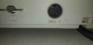

20200519_165519.jpg
 
The only video input on the monitor is what I'm almost certain is S-Video.

That looks like a full-size DIN connector to me, not an S-Video Mini-DIN. (Also note: S-Video makes no sense on a monochrome monitor because the difference between composite and S-Video is the latter separates the "Luma" brightness signal from the "Chroma" color signal. By definition a mono monitor only cares about "Luma".) If I had to hazard a guess it's probably a TTL input that happens to have a proprietary shape. Is there an actual model number anywhere on the monitor? I think you'll have to track down the manual to figure out what the pinout of that thing is.

(Searching for "Philips Computer Monitor 80" netted a youtube video showing a different model that has separate composite and sound plugs on the back. It would definitely not be unprecedented for Phillips to use a DIN plug for a digital input; several models in the Commodore 1084 monitor line were OEMed from Philips and use two different DIN plugs for RGBI and RGB-A respectively. It's unfortunate that the matching adapter cable for your setup has gone missing.)

On the computer end I would probably guess that your "CGA/EGA" card is actually an MDA/Hercules card, as that would align with the mono monitor. The bigger port that "looks like a parallel port" probably is one, it was pretty common for them to be integrated on Mono cards. (And some CGA cards have them too, so far as it goes.)

Thanks for the info! On one of the stickers on the back of the monitor it does say "TYPE BM7513/72I"; It appears this is the model number, and a quick google brought up the monitor itself! This is my first experience with a Monochrome monitor, so I'm pretty in the blind here. The only thing I'm certain of about it is that it's a green monochrome monitor, as turning it on reveals a green screen.
 
It appears as though the video output there is the Commodore standard for the 128; so I think I should be able to purchase a Commodore 128 cable and it'll work just fine!
 
Here's a copy of the service manual for it. It confirms that it's an MDA frequency mono monitor. The pinout is on page 17, if I'm reading it correctly the cable you want would involve:

Signal: Monitor -> DB9
GND: 3,6 -> 1,2
Intensity: 4 -> 6
Video: 5 -> 7
Hsync: 1 -> 8
Vsync: 2 -> 9

I don't think this was actually sold for use with the 128, it looks like it was targeted at the Commodore PC compatibles. (that's its stated application here.) You might be better off making your own cable; it looks like, in typical commodore fashion, Commodore confusingly also sold a *color* "1901", and a cable for it is unlikely to work.
 
If you can solder at least a little it's not too hard, although it can be tricky to get the pins in the connectors hot enough to get the solder to stick without melting the plastic. (It helps to plug the connector you're soldering on into an example of the matching socket; that way even if you soften the plastic a little hopefully the mating plug will hold it in position as it rehardens.)

I'd mostly be worried that this particular cable is going to be a really rare bird. Probably the only people likely to have one are those who specifically collect Commodore PC clones, which is a pretty select bunch.

Ahh alright. I have a friend who's good with soldering so I'll get him to give me a hand (I've never tried before). I know basically nothing about cable internals, how exactly will I know what I need to get and where everything needs to be soldered to?
 
For the computer end you'll need a male DB/DE9 connector, preferably with a matching hood and strain relief. IE, like in this kit:

https://www.amazon.com/XLX-Connectors-Complete-Connector-Assortment/dp/B076HPV4WJ/

DIN plugs can be tricky because a DIN with a given number of connector pins might use a different spacing. Based on the picture it *looks* like this one will fit:

https://www.amazon.com/Uxcell-a15101200ux0738-Each-Pack-4/dp/B018TH2OWM/

(This happens to be the same plug that a Tandy 1000 uses for its joysticks so I've actually bought this particular item before.)

The connectors will have the pin numbers cast into the plastic. Make sure, particularly on the DIN end, that the numbering is the same; sometimes companies use nonstandard pin assignments in their manuals, compare it to the picture in the manual. Then use a cable, preferably shielded, with at least six contacts to connect the two ends. Not a whole lot more to it.

Ok gotcha! So I assume now I'll just need to find said cable, grab those two items, and then away we go. Does it matter what particular kind of cable, or just the contacts you mentioned above? And finally, how do those DIN connectors come apart to solder, is it just a quick and easy removal of the black plastic casing?
 
Ok gotcha! So I assume now I'll just need to find said cable, grab those two items, and then away we go. Does it matter what particular kind of cable, or just the contacts you mentioned above? And finally, how do those DIN connectors come apart to solder, is it just a quick and easy removal of the black plastic casing?

I had to make a CGA cable not that long ago to go between my Tandy 1000 and a Commodore 1084, for the cable I cut the ends off an old VGA KVM cable that had nice thick insulation on it. So, yeah, if you have any lying around an old VGA cable is a pretty good source of multi-conductor shielded cable. Since this is a digital signal shielding probably isn't *that* critical, you could probably get away with just about anything if it were short enough, but better is better.

As for the DINs, yeah, basically the soft plastic hood with the tail on it slides back from the plug itself, it's all pretty straightforward. Just don't forget to thread the cable through the hood *before* you solder the ends on so you can slide it into place when it's all done, I made that forehead-slapping mistake once.
 
I like to use sections of stranded cat5 cable for stuff like that, sometimes threaded though a ferrite bead on each end to help reduce the rfi, sometimes more than one section if I need more than 8 conductors. If you have spare wires, can also run a signal on one wire of a twisted pair and ground the other to help keep the noise out. Probably not as good as an expensive shielded cable, but works well enough for me. :3
 
Back
Top