• Please review our updated Terms and Rules here

Searching for NEC PC-8001A software & hardware

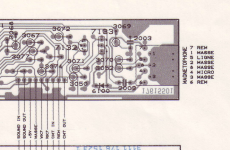
Ah, but without the diagrams, it's not obvious (to me) what the pinout order is (at least not being a DIN connector expert; like in that Japanese user manual the clockwise order of the CMT pins from 1 is 1-4-2-5-3-7-8-6. Also in that manual is the currently the only photo of that RS232 ribbon cable that I've come across!

I've got some diagrams of pinouts including the PC-8001 here:

https://vintagecomputers.sdfeu.org/general/leads.html

Note a MSX cassette lead should work fine.

Regards,
John
PS DIN connectors are described here: https://en.wikipedia.org/wiki/DIN_connector (so thanks WP for the diagrams)
 
Last edited:
Thanks for the fix!

Unfortunately, a second upload under a new item name/URL (identical to my upload except for the hyphen between "8001" and "b") can be a bit confusing, especially for those who referenced the original URL. The filenames are the same, too, which means if you have a downloaded copy you can only tell whether you have the original or corrected version by examining the file itself.

(Also, it's probably worth mentioning that your publication date field, 2024-03-29, is wrong; the manual was published in 1981.)

Sadly, archive.org doesn't provide a huge amount of help for dealing with provenance and distinguishing multiple uploads. But to help current and future users, I've uploaded your new scan on my item as well, but also renaming the file from PC-8001B Micro Computer User's Manual (NEC, en, 1981).pdf to PC-8001B Micro Computer User's Manual (NEC, en, 1981, scan2).pdf. (I did this by adding the new file and deleting the old file and its derivations in that item using the "Edit" options for the item.) And I've also linked to your item.

Thanks for the referencing work !
I've also corrected the publication date.
Carl
 
  • Like
Reactions: cjs
cable k7.jpg

Hi,
I use the msx tape cable to connect the headphone output of my PC laptop to the NEC 8001 (pin 5) and play a wav file to load a program...
Carl
 
This diagram is incorrect: pin 7 is not ground, and the sleeve of the remote connector should be connected to pin 7, not ground.

BTW, another reference for DIN connectors (CMT and video) on many Japanese computers is this Retrocomputing Stack Exchange answer. (And that also includes pin numbering diagrams that indicate which connector and in which direction you're looking at it. It, as above, uses the "looking into the female connector on the computer" view.)
 
Well, REM (remote) isn't critical - you just have to be more mindful of pressing STOP yourself after done loading.

I just got one of the NEC PC-8001 VGA adapters - works great, so I can use a modern flat panel and not put more wear-and-tear on the CRT.


INKEY, can't believe I missed that scrolling through the English version of the N-BASIC manual. Thanks. That said, I think the documentation for the INPUT% (RS232 support variant of that command) isn't in the BASIC manual, it's in the TERM notes in some other manual. The GPS and mount controls on my Celestron mount are still RS232, that'd be wild to be able to control that from the PC-8001 through N-BASIC. Ah, but they use 9600 baud
https://www.nexstarsite.com/PCControl/ProgrammingNexStar.htm
I know an "inefficiently implemented" terminal might not be able to keep up with the hardware supported baud rate (you see on this some systems like when you start to lose characters only when the system is scrolling at the bottom of the screen, when it is doing "more than usual" amounts of work to scroll the text screen). Or this is why some systems can't support ANSI, the "stress" of converting those codes on the fly is too much (or just not efficiently implemented). Even simple ASCII to local-display-code conversion can stress some systems. I'm not sure if any of that is why the PC-8001 TERM appears to be limited to 600 baud (or it'd be nice to hear/confirm if others encountered a similar limit, or if other users have used the built in TERM at higher baud rates).

I don't think anything on the WiModem232 side would be causing the issue - also, to clarify, I was using the PC-8001 MK II (because I didn't want to open the PC-8001 and change the internal jumper). But the PC-8001 MK II is using a "full" DB25 connector (meaning all the RS232 lines are connected, like the RTS/CTS stuff-- not sure if that matters).


Also, PCBWAY is saying they can make one of these SD-card drive emulators, but they need Gerber files?? I'm not entirely sure how to do that or what they are looking for. Is it just a conversion of the format used in this github repo? Anyone know how to do this?
 
Also, PCBWAY is saying they can make one of these SD-card drive emulators, but they need Gerber files?? I'm not entirely sure how to do that or what they are looking for. Is it just a conversion of the format used in this github repo? Anyone know how to do this?
Assuming this is the latest version, they have provided a zip of the Gerber files here: https://github.com/yanataka60/PC-8001_SD/tree/main/Kicad1_4/PCB (last file in the listing.) Usually I put my gerbers in the "Releases" section on GitHub but this also has confused folks in the past, so maybe there's no good place for it! 🤔

Gerber format files for PCBs are sort of like the G-code or plotter instructions for the various layers, you can usually generate them from a KiCad file using the "Plot" command in the PCB editor.
 
Well, REM (remote) isn't critical - you just have to be more mindful of pressing STOP yourself after done loading.
Right, but it's still nice not to have wrong information kicking around on the Internet for those who are trying to build a cable that does use this.

That said, I think the documentation for the INPUT% (RS232 support variant of that command) isn't in the BASIC manual, it's in the TERM notes in some other manual.
In my BASIC quickref I keep notes on sources; I got the TERM information from various sources (it changes between N/N80- and N88-BASIC), but the INIT% and the like came from page 51 of the English Users Manual.

The GPS and mount controls on my Celestron mount are still RS232, that'd be wild to be able to control that from the PC-8001 through N-BASIC. Ah, but they use 9600 baud
The serial clock (SCLOCK) is derived from the system clock divided down via counters. You can see this on PDF page 7 of the schematics: ΦS comes in at the left, goes to the CLK input of the serial chip (which is not the serial clock!), and also down, across and up again to IC54 and IC87 which do the division. A mod to give you a 9600/2400 for the ×64/×16 dividers on the UART may be as simple as connecting pin 11 (Qd) of IC54 to pin 1 of CN8 (the clock rate jumper), though I'd want to check that with a 'scope to be sure.

I know an "inefficiently implemented" terminal might not be able to keep up with the hardware supported baud rate.... I'm not sure if any of that is why the PC-8001 TERM appears to be limited to 600 baud (or it'd be nice to hear/confirm if others encountered a similar limit, or if other users have used the built in TERM at higher baud rates).
I am pretty sure that something else is going on there, or TERM is particularly inefficient (though I can't see why it would be). On early PC-8801 models where they have hardware clock support to run the serial port at higher rates I've used xdisk2 and xdisk3 at 19,200 and even, IIRC, 38,400 bps.

I don't think anything on the WiModem232 side would be causing the issue - also, to clarify, I was using the PC-8001 MK II (because I didn't want to open the PC-8001 and change the internal jumper). But the PC-8001 MK II is using a "full" DB25 connector (meaning all the RS232 lines are connected, like the RTS/CTS stuff-- not sure if that matters).
The PC-8001 has all of those signals on the internal header as well; again, see my docs for details. Per the user manual linked below, the PC-8001mkII is roughly the same thing as a PC-8001 plus the PC-8062 RS-232 cable.

But if you're using the PC-8001mkII the bps rate setting has been moved from an internal jumper block to an external one on the back and they've added support for 9600/2400 bps. The settings are on page 9-4 of the user manual. (That's showing the external header next to the DIP switches.)
1712104191023.png
 
What happens when you press F6? That toggles "visible control code" display.
I recall trying that - and it would toggle the display of things like "CR", but the "BS" symbol seemed to appear in either case.


As for the baud rate jumpers on the PC-8001 MK II, I've assumed it is ok to adjust those while the system is running? The WiModem232 I have defaults to 300 baud on its power up. So I started at 300, then AT*Bn to adjust baud rate, and increment the jumper accordingly. It does "work" at 1200, but typing ATI (status) you start to see many missing characters, gradually getting worse (more dropped/missing characters) at the higher baud rates. (so I should have clarified - not that it doesn't work at all, just increased likelihood of dropped characters -- I did try AT&C1 or 0, i.e. toggling the RTS/CTS flow control of the WiModem232 device, but not completely sure I was doing that correctly {like if it needs a restart between adjustments?})
 
As for the baud rate jumpers on the PC-8001 MK II, I've assumed it is ok to adjust those while the system is running? The WiModem232 I have defaults to 300 baud on its power up. So I started at 300, then AT*Bn to adjust baud rate, and increment the jumper accordingly. It does "work" at 1200, but typing ATI (status) you start to see many missing characters,
I would think it's ok to change the baud jumper on the fly, but I'm not totally certain. If you're having issues after doing that, it may be worth resetting the PC-8001 after changing the jumper. But if you're just changing from 300 to 1200, there's no need to do a jumper change: you can simply jumper it for 1200/300 and then switch from a baud rate divisor of 64 to 16. I.e., run TERM 8,0,0, send the command to the modem to switch from 300 to 1200 bps, exit TERM (with Ctrl-B or Graph-B), and start again at the higher rate with TERM 8,0,1.

You might also try it through a crossover adapter to a USB serial interface on a modern computer, and see if you have the same issues there, just to confirm that it's not an issue with the modem.

I guess I'll need to dig out my PC-8801mkII and see how TERM works for me, to see if it might be just some sort of a problem with your machine. It would seem odd if TERM itself is at fault, since it ought to be a pretty darn simple and fast program....
 
It's the same WiModem232 I used here on the CoCo3 at 19200 baud (with 6551 chip). The onboard PIA 6821 of that system was hard to bit bang past 2400. But yeah, I'd imagine the PC-8001's 8251 UART should be a tad more performant.


Anyone happen to be aware of any other cassette based terminal software for the NEC system?


On the MK II, is Mode Select DIP #8 the only one that does anything? (loads the older N-BASIC ROM instead of the Enhanced?)
 
IOn the MK II, is Mode Select DIP #8 the only one that does anything? (loads the older N-BASIC ROM instead of the Enhanced?)
Switch 8 only one mentioned in the manual, IIRC. I'd love to have a look at the schematic to see what else might be hooked up there, but I don't have a copy of it. There's a moderately good chance that some issue of I/O magazine from 1983 or 1984 has it, though, so it might be worth poking through those on archive.org to see if you can find the issue. If you do, let me know and I'll extract the appropriate pages and add them to my pc8001-re repo. (I/O also publishes "活用研究" books that are reprints of stuff from the magazine; if you can find one of those for the 8001mkII, that will have the schematic if they ever did one.)

EDIT: I did find their one book that seems to cover the PC-8001mkII, I/O別冊 PC活用研究 8001/8001mkII/8801. Sadly, this doesn't have any schematics for the machines in it. It may be that they just didn't want to include them, since they'd already republished the PC-8001 schematics in PC-8001活用研究. So it still might be worth a magazine search.
 
Last edited:
This diagram is incorrect: pin 7 is not ground, and the sleeve of the remote connector should be connected to pin 7, not ground.

BTW, another reference for DIN connectors (CMT and video) on many Japanese computers is this Retrocomputing Stack Exchange answer. (And that also includes pin numbering diagrams that indicate which connector and in which direction you're looking at it. It, as above, uses the "looking into the female connector on the computer" view.)
Hi cjs, that's right, but I don't use pin 7.
So MSX cable is ok for my connection between laptop and Nec 8001...
din nec8001.jpglaptop nec8001.jpg

Carl
 
Hi cjs, that's right, but I don't use pin 7.
So MSX cable is ok for my connection between laptop and Nec 8001...
Well, yes the MSX cable is fine even if you do use the relay (pins 6 and 7) because it's wired to the same standard. It was just your diagram that was wrong. (Virtually all Japanese microcomputers of the late '70s and early '80s use the exact same DIN-8 pinout for CMT.)
 
Well, yes the MSX cable is fine even if you do use the relay (pins 6 and 7) because it's wired to the same standard. It was just your diagram that was wrong. (Virtually all Japanese microcomputers of the late '70s and early '80s use the exact same DIN-8 pinout for CMT.)
OK, i understand, my diagram is for the Philips VG5000 cable and is not fully compliant with the msx standard, Philips msx standard from VG8000 onwards...
 
Assuming this is the latest version, they have provided a zip of the Gerber files here: https://github.com/yanataka60/PC-8001_SD/tree/main/Kicad1_4/PCB (last file in the listing.) Usually I put my gerbers in the "Releases" section on GitHub but this also has confused folks in the past, so maybe there's no good place for it!

"we need Gerber file for PCB, BOM file and pic&place file for assembly."

Thanks, I see now for Kicad.
I assume BOM is "bill of material", an inventory of IC's and pin headers? Plus I think there is one switch in the build. A few of the components are obvious from the photos, but didn't see a complete list.
Not sure on the other info needed. But I'm certainly up for a trial run to test :)
 
The parts of the BOM appear to be in this section of the readme at the root of the repository. The heading "部品" roughly translates to "parts."

Note that version 1.4 (the Gerber I linked you to earlier) requires an additional connector at J5 which is described later in that section; don't miss it! (I would, if it were me.)

Most of the part numbers are coming from Akizuki Denshi, which is a retail hobbyist electronics chain in Japan (think '80s Radio Shack, but much better.) It can be difficult to find equivalent parts on Digi-Key, etc in the West, especially for large stuff like their SD card reader module and their custom Arduino "Pro Mini" whose pinout doesn't match AliExpress' Arduino Pro Minis (something that has bit me in the butt in the past.)

If you have no other option, you can source the parts from Akizuki Denshi using a package proxy like zenmarket.
 
OK, i understand, my diagram is for the Philips VG5000 cable and is not fully compliant with the msx standard, Philips msx standard from VG8000 onwards...
That diagram does not appear to be for the VG5000, from a look at page 6 of the service manual.

And it's worth noting that any CMT interface diagram with only one REM or "Remote" pin is almost certainly incorrect. The remote works by inserting the the two REM pins into the motor drive current or similar line, so that a relay can close and open that connection to turn the motor on and off.
 

Attachments

  • 1712296472032.png
    1712296472032.png
    644 KB · Views: 4
Has anyone gotten the Mario Special for this NEC running on hardware? It seems to be a "dual loader" where it first loads a typical BASIC program, that then runs a "fancy loader." This second loader seems to use a different "protocol" (or format) and may be more sensitive to volume setting (on physical hardware).

Oh, to clarify, I think it needs a PC-8001 Mk II, not the actual original system.
 
Back
Top