NeXT
Veteran Member
Way back in 2017 I followed up on by first entry into Mastervoice and their Butler in a Box ( https://forum.vcfed.org/index.php?threads/stuck-in-the-80s-mastervoices-butler-in-a-box.1070062/ ) with their follow-up product before Mastervoice folded and disappeared entirely, the Mastervoice ECU. ( https://forum.vcfed.org/index.php?threads/mastervoice-ecu-the-butler-in-a-box-tries-again.1070407/ )
To bring everyone up to speed, the Butler in a Box and the ECU were the 80's equivalent to the Amazon Alexa or Google Home Assistant. It was a box that you could speak to and with training it could recognize your voice and be commanded to perform a variety of tasks. It was also able to control a very large selection of X10 products as well as operate more specialty controls such as relay banks through a parallel port (which the manual states is *not* a traditional PC parallel port) while also taking commands over the phone and providing some simple security system functionality. It was obviously expensive but very advanced.
Along with being such an advanced product came its own security. Much like a car stereo you found in the 90's, the first time you power it on it will perform a self-test, then prompt for a PIN.
This was how Mastervoice made sure that stolen units could not be resold. If the backup battery fails/is missing and power is lost it will always come up and prompt for the PIN. The PIN is a four character alphanumeric code (0-9, A-Z) normally written in the manual. A copy of said manual can be found here: ( https://archive.org/details/mastervoice-butler-in-a-box-manual-pages )
Mastervoice could provide you with the PIN should you of lost it back in the day, but 30 years later that option is long gone. If you are going through ebay and see a Butler in a Box, hope you see the manual or the PIN written on it or it's no more useful than a bookend. Obviously the PIN is stored on a ROM inside the Butler in a Box, but where?
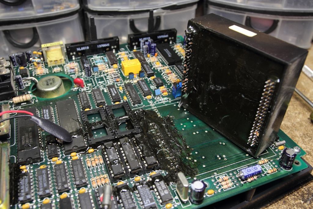
Inside any Butler in a Box or ECU you will find a UV programmable Intel 8748 (MCS-48 microcontroller) seemingly handling the telephone functionality, a pair of 27256 EPROMs I would not necessarily call secure and a large black brick. This brick will have a tag stating it's from Mastervoice, messing with it voids the warranty, the product that it's for, the model and the serial number. Seeing how there is no sign of the main CPU on the board anywhere else it is safe to assume it's inside this box, however the box connects to the board using over 75 pins and is itself quite large, so it is safe to assume there is more than a CPU hiding inside, specifically since the box is serialized, the PIN will be stored in this box on a ROM.
That I am aware of nobody up to this point has gone this far into figuring out how these things tick, in part because doing so will likely destroy the module and render the entire unit unusable. However if we remember from my ECU, then the box was initially filled with a potting compound to keep snoops out, the resin failed to properly cure. The resulting mess meant the unit did not work, but also that depotting the module would be easier than normal. Now that I've had some time with depotting and cleaning following my previous adventure with the AMC CeC I decided there was nothing to lose and gave it a go.
The first task was removing the module. This turned out to be far less pleasant than I expected. The solder on the module's pins were stubborn and heating up the pins would cause softened resin to be sucked into the holes. Ultimately the only solution was heat and more prying force than I was really wanting to apply. Eventually, the module came free, along with a half dozen traces...
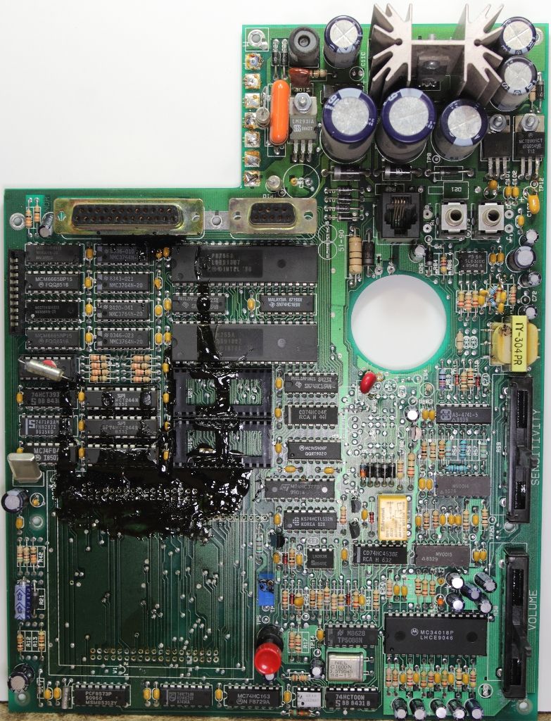
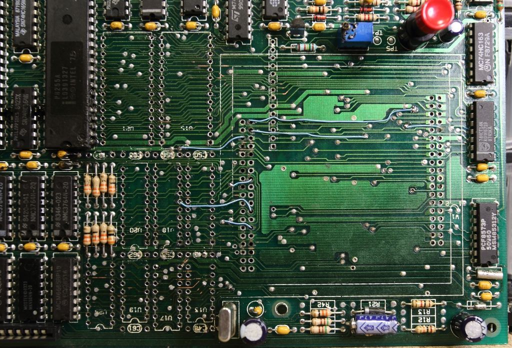
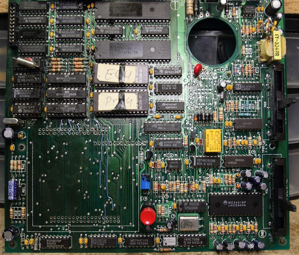
The module was set aside and the board cleaned up. All the chips in the affected area were pulled, the board cleaned with hot air, a knife and acetone and new sockets were installed. Broken vias were patched and pulled traces were trimmed and new bodge wires run.
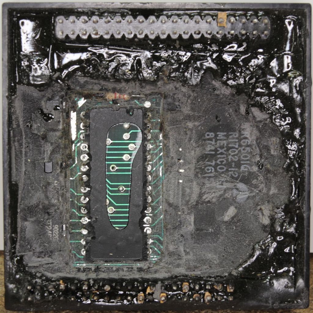
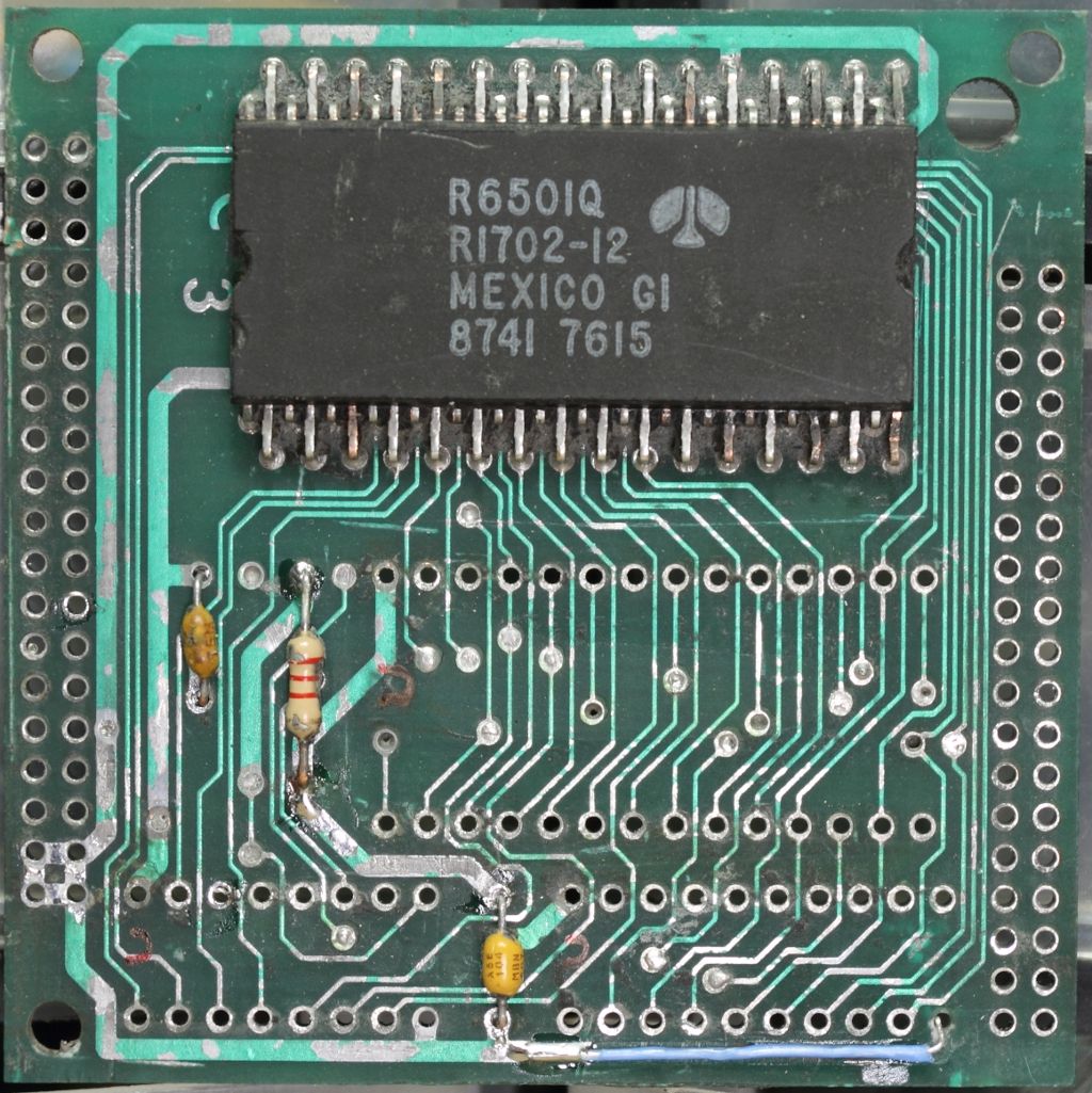
Now that the unit at least was probably in a working condition my attention went back to the module. The first order was to heat up some of the potting compound and start exploring. In short order, the window of an EPROM appeared, then the numbers from a Rockwell R6501Q microprocessor came into view. Quickly I considered my chances both sides of the PCB inside the module were populated, then took a dremel to behind the EPROM and desoldered it for dumping. It's a 2764.
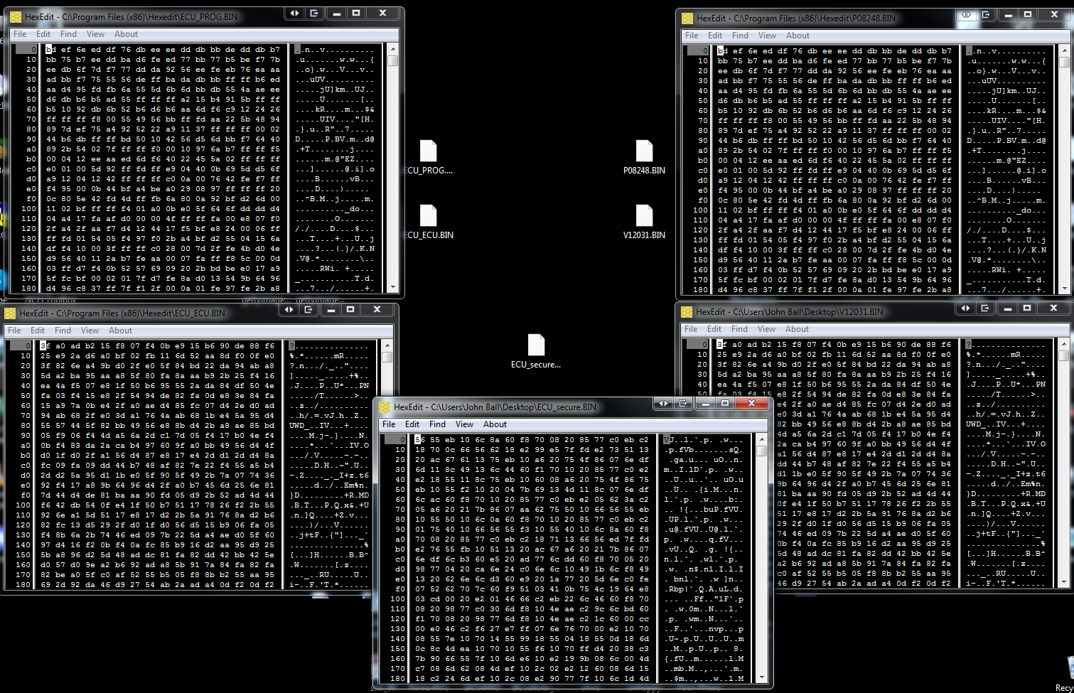
Now I had FIVE EPROM images. The first two were the EPROMS from my original Mastervoice Series II, then the two EPROMs from the ECU and now this EPROM buried inside the security module.
The EPROM labeled "P08248" and "PROG" in the two units had a matching checksum A703
The EPROM labeled "V12031" in the Butler had a checksum of 2A76. The EPROM labeled "ECU" in the other had a checksum of 092B. At a glance in the editor they still however look very similar.
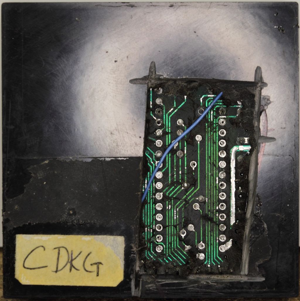
This new EPROM pulled out of the module (Which I will from here on call "CDKG") had a checksum of 305B but we have nothing to compare it against.
Copies of these dumps can be found in a ZIP file attached this post (as of 2023).
Curiously as I was extracting the secure EPROM I noticed other chips inside the potting as well. Figuring I had gone this far in already and I was now far past the point anyone else had ever gone I decided it was worth the effort to completely remove the potting and see what other secrets were revealed. The process would take some seven hours.
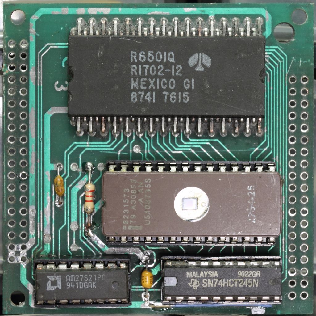
Beyond one bodge wire on the backside, the potting revealed an SN74HCT245N tri-state octal bus transceiver and an AM27A21PC 256 x 4 1024-bit bipolar PROM.
Man. I got no problems reading fairly standard EPROMs but a PROM like that? How the hell do you even *write* one of those?? Why is this even in here if you already have space for an EPROM??
My guess is that this PROM is being used as additional path logic, but as of right now I have yet to start looking how it interacts with the CPU and the ROM. Is it obfuscating the data bus for the EPROM to prevent it being easily dumped? Is the PIN stored in here? I feel like to proceed much further will require safely dumping that PROM and to go back and verify every other ROM I've dumped so far on the Series II was done cleanly. I can at least say the ones in the ECU were read back good. Clearly we can see that one set matched. The other is close, but something different. More research will need to be done but at the very least we've finally seen for the first time what Mastervoice was hiding inside this module and perhaps we are that much closer to finding a solution for all those systems still out there where the PINs have long been lost.
To bring everyone up to speed, the Butler in a Box and the ECU were the 80's equivalent to the Amazon Alexa or Google Home Assistant. It was a box that you could speak to and with training it could recognize your voice and be commanded to perform a variety of tasks. It was also able to control a very large selection of X10 products as well as operate more specialty controls such as relay banks through a parallel port (which the manual states is *not* a traditional PC parallel port) while also taking commands over the phone and providing some simple security system functionality. It was obviously expensive but very advanced.
Along with being such an advanced product came its own security. Much like a car stereo you found in the 90's, the first time you power it on it will perform a self-test, then prompt for a PIN.
This was how Mastervoice made sure that stolen units could not be resold. If the backup battery fails/is missing and power is lost it will always come up and prompt for the PIN. The PIN is a four character alphanumeric code (0-9, A-Z) normally written in the manual. A copy of said manual can be found here: ( https://archive.org/details/mastervoice-butler-in-a-box-manual-pages )
Mastervoice could provide you with the PIN should you of lost it back in the day, but 30 years later that option is long gone. If you are going through ebay and see a Butler in a Box, hope you see the manual or the PIN written on it or it's no more useful than a bookend. Obviously the PIN is stored on a ROM inside the Butler in a Box, but where?
Inside any Butler in a Box or ECU you will find a UV programmable Intel 8748 (MCS-48 microcontroller) seemingly handling the telephone functionality, a pair of 27256 EPROMs I would not necessarily call secure and a large black brick. This brick will have a tag stating it's from Mastervoice, messing with it voids the warranty, the product that it's for, the model and the serial number. Seeing how there is no sign of the main CPU on the board anywhere else it is safe to assume it's inside this box, however the box connects to the board using over 75 pins and is itself quite large, so it is safe to assume there is more than a CPU hiding inside, specifically since the box is serialized, the PIN will be stored in this box on a ROM.
That I am aware of nobody up to this point has gone this far into figuring out how these things tick, in part because doing so will likely destroy the module and render the entire unit unusable. However if we remember from my ECU, then the box was initially filled with a potting compound to keep snoops out, the resin failed to properly cure. The resulting mess meant the unit did not work, but also that depotting the module would be easier than normal. Now that I've had some time with depotting and cleaning following my previous adventure with the AMC CeC I decided there was nothing to lose and gave it a go.
The first task was removing the module. This turned out to be far less pleasant than I expected. The solder on the module's pins were stubborn and heating up the pins would cause softened resin to be sucked into the holes. Ultimately the only solution was heat and more prying force than I was really wanting to apply. Eventually, the module came free, along with a half dozen traces...
The module was set aside and the board cleaned up. All the chips in the affected area were pulled, the board cleaned with hot air, a knife and acetone and new sockets were installed. Broken vias were patched and pulled traces were trimmed and new bodge wires run.
Now that the unit at least was probably in a working condition my attention went back to the module. The first order was to heat up some of the potting compound and start exploring. In short order, the window of an EPROM appeared, then the numbers from a Rockwell R6501Q microprocessor came into view. Quickly I considered my chances both sides of the PCB inside the module were populated, then took a dremel to behind the EPROM and desoldered it for dumping. It's a 2764.
Now I had FIVE EPROM images. The first two were the EPROMS from my original Mastervoice Series II, then the two EPROMs from the ECU and now this EPROM buried inside the security module.
The EPROM labeled "P08248" and "PROG" in the two units had a matching checksum A703
The EPROM labeled "V12031" in the Butler had a checksum of 2A76. The EPROM labeled "ECU" in the other had a checksum of 092B. At a glance in the editor they still however look very similar.
This new EPROM pulled out of the module (Which I will from here on call "CDKG") had a checksum of 305B but we have nothing to compare it against.
Copies of these dumps can be found in a ZIP file attached this post (as of 2023).
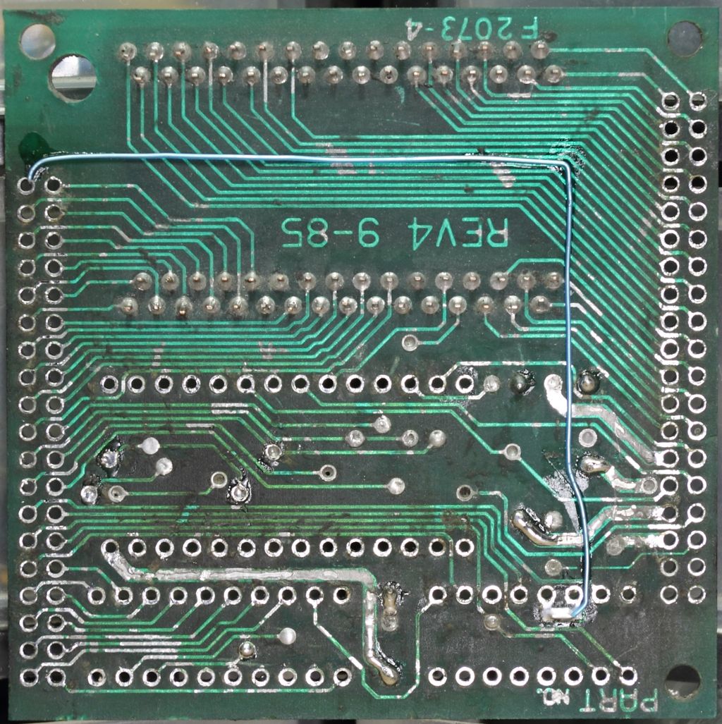
Curiously as I was extracting the secure EPROM I noticed other chips inside the potting as well. Figuring I had gone this far in already and I was now far past the point anyone else had ever gone I decided it was worth the effort to completely remove the potting and see what other secrets were revealed. The process would take some seven hours.
Beyond one bodge wire on the backside, the potting revealed an SN74HCT245N tri-state octal bus transceiver and an AM27A21PC 256 x 4 1024-bit bipolar PROM.
Man. I got no problems reading fairly standard EPROMs but a PROM like that? How the hell do you even *write* one of those?? Why is this even in here if you already have space for an EPROM??
My guess is that this PROM is being used as additional path logic, but as of right now I have yet to start looking how it interacts with the CPU and the ROM. Is it obfuscating the data bus for the EPROM to prevent it being easily dumped? Is the PIN stored in here? I feel like to proceed much further will require safely dumping that PROM and to go back and verify every other ROM I've dumped so far on the Series II was done cleanly. I can at least say the ones in the ECU were read back good. Clearly we can see that one set matched. The other is close, but something different. More research will need to be done but at the very least we've finally seen for the first time what Mastervoice was hiding inside this module and perhaps we are that much closer to finding a solution for all those systems still out there where the PINs have long been lost.