• Please review our updated Terms and Rules here

SFD-1001 alignment.

Hugo Holden

Veteran Member
Joined
Dec 23, 2015
Messages
4,790
Location
Australia
I have a perfectly working SFD-1001, that is to the extent that it formats and writes disks fine and there are no issues reading what it has written.

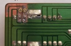
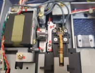
When I got the unit though I was suspicious that somebody had been working on the 5.25 drive unit in the past, because of tooling marks on some of the screw heads.

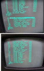
In any case I bought a SFD-1001 Demo Disk which the seller claimed was perfect and worked in the units. It did not work and the green light starts flashing red, the computer hangs and the drive makes a semi-violent buzzing sound the light then stays red and is only cleared by power cycling.

I thought it might have been bad luck, so I bought another Demo disk, exactly the same.

So I think the heads in the drive must be way off standard alignment.

The thought occurred to me that I could use the Demo disks as an alignment disk, as they must be pretty close to standard alignment if they play in other SFD 1001's (which the sellers assured me they did).

I have all the tools required and the drive's manual (doesn't have a full schematic), scope etc but I would like some advice before attempting it from somebody who has already done it, if possible. And three initial questions:

1)Since the drive wont run the demo disk, and goes it an error/lockout mode, how can I fool it into continually running the disk ?

2) Where is the best place to monitor the disk output, immediately after the head preamp ? (I don't have the full schematic yet, still looking)

3) For this unit, it looks to gain access I would have to remove the drive from its mounts and move it out of the unit, are any extension connectors required in this case ?


Thanks for any advice & help.

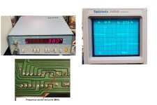
( also wonder if it is possible to get this sort of effect if the spindle speed is off standard ?)

I found the schematics on Zimmers:


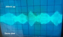
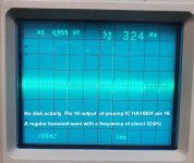
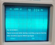
I recorded some signals out of the head preamp. With a disk that the drive recorded there is a good 200mV pp signal out of the head preamp. With both the Demo disks it is low at only about 100mV pp and pulsing up and down a little. When the drive starts to make loud noises, some triangular patterns appear before the disk stops.

I also checked the digital output of the preamp Ic, when its playing its own disks there appears to be regular data pulse stream, with the Demo disks it just looks like noise and nothing definite.

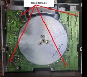
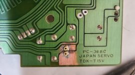
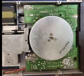
The actual drive unit, from the look of the information I can find is the JU-570.

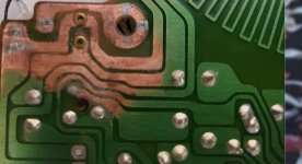
One other thing, it looks like somebody has applied oil to the drive, because it is appearing on the floppy disk hubs, not a huge amount but its there.
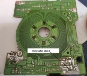
 

Attachments

  • scope1.jpg
    scope1.jpg
    242 KB · Views: 5
  • scope2.jpg
    scope2.jpg
    157.6 KB · Views: 5
Last edited:
further........another recording on a different scope, sorry about the quality I cut it out of a video.

Most of the time the signal out of the head amplifier on the Demo Disk is very low, actually less than 100mV more like <30mV when the computer initially starts looking/loading a file (whereas that out of a disk the the SFD unit recorded itself is a solid 200mV).

But at times when the computer is searching for a file, if I ask it to load an imaginary file from the Demo disk, there is data on the demo disk, it appears, because it produces patterns sometimes, especially with the sound of the head hunting around, that looks like the head is crossing over disk tracks and the signal level comes up to 200mV pp which is probably a normal level:

So it does appear the head alignment is off in my SFD-1001 with respect to the Demo disk, the question is how to move it to the correct position. Obviously the level needs to be peaked on the scope with mechanical movement of the head, but I have not done this on a disk drive yet (but plenty of tape decks and VCR's heads).

(one of the reasons the first scope recordings were fuzzy, was that it was a 400MHz scope and I didn't have the 20MHz bandwidth limit switch on)
 

Attachments

  • scope3.jpg
    scope3.jpg
    160 KB · Views: 2
Well, I am starting to get to the bottom of why my JU-570-2 disk drive in the SFD-1001 is out of alignment. The person who worked on it in the past was an idiot.

An ebay seller I am afraid, and I'm almost tempted to say who they were.

I removed the drive. I inspected the mounting screws, the wrong sized screwdrivers were used and the screw heads were torn up.

It looks like the motor drive controller board was removed for some sort of very very lame attempt at re-capping. Also it looks like some corrosive acid flux was used on the pcb. (see photo)

What I think has happened here, is the standard alignment was thrown off by the spindle drive being removed an re-fitted, which changes the relative mechanical alignment with the heads.
 

Attachments

  • SFD5.jpg
    SFD5.jpg
    230 KB · Views: 12
I thought the better move would be to reapiar the pcb first, then measure the spindle speed, before even dreaming about altering the Head position.

I have attached some photos. I don't think the pcb ended up the way it was due to leaked electrolytic capacitors. The reason being that there are no plated through holes, it is a single sided board. So that any leaked electrolyte would be on the phenolic side opposite to the tracks. So I am fairly certain acid flux was applied to the pcb.

In any case it was quite a repair job. I fitted miniature brass eyelets to the pcb where the pads and tracks had lifted. I used 1000 grade paper on the pcb. And there was a lot of cleaning required.

The photos tell the story.

Now, I am working on the Head alignment issue, but here is an interesting thing:

While I had the motor control pcb out of the unit, I noticed that the flexible pcb, that feeds power to the LED, that works the index hole, had been torn up. So The LED would not have been working.

I repaired that, and also checked the LED current, which was about 35mA. Seemed well and good. But on the phototransistor side of things, sent to the SFD main board, I noticed that was not powered. Looking at the SFD-1001 schematic, it is not used. Imagine that ? The index hole is not used by the "computer" that is the SFD-1001, that controls the 5.25" drive. That surprised me.

But I am considering powering the phototransistor, to be able to measure the RPM (I don't have a strobe). If the speed of the motor is correct at 300RPM, it should be a 5Hz signal.
 

Attachments

  • BRD1.jpg
    BRD1.jpg
    268.4 KB · Views: 15
  • BRD2.jpg
    BRD2.jpg
    137.3 KB · Views: 14
  • BRDA.jpg
    BRDA.jpg
    82.5 KB · Views: 13
  • BRDB.jpg
    BRDB.jpg
    135.6 KB · Views: 10
  • BRDC.jpg
    BRDC.jpg
    179 KB · Views: 15
  • BRDF.jpg
    BRDF.jpg
    257.8 KB · Views: 15
  • DRVF.jpg
    DRVF.jpg
    184.3 KB · Views: 15
Last edited:
Yes, commodore dont seem to have been a fan of the index sensor. In the 8050 drives, neither the LED or the sensor are fitted to the drives.
 
I thought the better move would be to reapiar the pcb first, then measure the spindle speed, before even dreaming about altering the Head position.

I have attached some photos. I don't think the pcb ended up the way it was due to leaked electrolytic capacitors. The reason being that there are no plated through holes, it is a single sided board. So that any leaked electrolyte would be on the phenolic side opposite to the tracks. So I am fairly certain acid flux was applied to the pcb.

In any case it was quite a repair job. I fitted miniature brass eyelets to the pcb where the pads and tracks had lifted. I used 1000 grade paper on the pcb. And there was a lot of cleaning required.

The photos tell the story.

Now, I am working on the Head alignment issue, but here is an interesting thing:

While I had the motor control pcb out of the unit, I noticed that the flexible pcb, that feeds power to the LED, that works the index hole, had been torn up. So The LED would not have been working.

I repaired that, and also checked the LED current, which was about 35mA. Seemed well and good. But on the phototransistor side of things, sent to the SFD main board, I noticed that was not powered. Looking at the SFD-1001 schematic, it is not used. Imagine that ? The index hole is not used by the "computer" that is the SFD-1001, that controls the 5.25" drive. That surprised me.

But I am considering powering the phototransistor, to be able to measure the RPM (I don't have a strobe). If the speed of the motor is correct at 300RPM, it should be a 5Hz signal.

I've happily used a phone app (Strobily in my case, but there's plenty of others) to act as a 'proper' strobe when fixing one of my Commodore 8050 drives.

Colin.
 
Thanks Colin & Gary.

I tried Strobily, the speed appeared to be very close, I made a small adjustment. I'm not much of a fan of using Apps as scientific instruments ever since a Compass App led me astray, but I suspect its close enough.

I have confirmed that the Demo disk is ok by applying a slight pressure bias to the stepper motor, I got it to load the demo disk.

But the thing is now , practical advice on how to slightly move the heads.

See photo attached.

I looked initially like the head had been arranged to slide on its mounts with the appearance of the slot in the metal (item C in the photo) and loosening the screws D & E, but close inspection shows this is not the case because there is a nub in a fixed hole item F.

So, it appears as though the position of the the stepper motor shaft with respect to the wheel could be adjusted by loosening screw at B, but I think likely that screw would be applied to a flat on the stepper shaft, or perhaps if there is some play in the flexible band mount at screw A but it looks unwise to touch the bands.

Or, should the whole steeper motor be moved by loosening screws G & H ?

Or something else I am missing ?
 

Attachments

  • Head.jpg
    Head.jpg
    193.9 KB · Views: 18
Thanks Powerlot.

All it took was to loosen the screws G & H and fractionally move the position of the stepper motor. This moves the relative position of the heads with respect to the spindle center.

It turned out that both of the Demo disks I bought had almost identical alignment , so I'm guessing that the average of those two will be pretty close to "standard". Now they both load perfectly.

Of course the previous disks I made in the SFD are now "out of alignment", but I had the sense before I started this escapade , to put those files on the SD2PET. So I can re-format all of my 5.25 disks now in the SDF unit and put the files back on them. I set the SD2PET up as device 8 and the SFD unit as device 9. So I can easily transfer files between the two. Might make one wonder why I wanted a Disk drive, it is the magic you see.

The SFD-1001 repair is now complete.

One other thing I noticed about the disk drive, the motor servo control is excellent.

It has a pcb track "coil" in the motor drive pcb, that picks up the field from the rotating ceramic magnet. This obviously is in a feedback loop with the motor drive amplifier. If you apply friction (and take some energy from the spindle ) under strobe light examination the RPM does not slow down, or speed up, so they did a very nice job designing the motor servo in this drive, and it is clearly better than any drive driven by a belt.
 
Last edited:
The manual says the mounting screws G & H

Ah, took too long to find it and Powerlot beat me to it.
 
I came to this a little late, but my guess would have been G because of the bent-up tab in the stamping just below it in the photo. That's where you insert the screwdriver and apply a little torque to push the motor mount up. There's probably a corresponding spot near H too, but that's not visible in the photo.
 
Last edited:
Some more observations with this Drive:

I noticed that the frequency generator "coil" on the pcb appeared to have around 75 to 76 turns if one considers the entry point loop. But I have no idea of the pole-piece arrangement on the rotating ceramic magnet.

But I figured there would have to be a fixed integer relation between the RPM (or 5Hz rotation frequency) and the signal generated by the coil. This is processed by an amplifier IC nearby. With the scope it was easy to find the amplified and squared up signal on the IC. With my scope cursors it was about 378 to 379 Hz (this was after the adjustment using the the phone strobe App)

While in the topic of the phone strobe App though, there appeared to be some speed jitter at time looking with the strobe, but the irregularity is in the frequency of the strobe itself at times, there are no irregularities or phase jitter of any significance at all from the frequency generator, it looks like perfectly stable rotation. The Phone App had resulted in a frequency of 379 Hz measured for the frequency generator signal, both on the scope and the frequency counter. The irregularities in the phone app strobe took like some event is randomly upsetting the strobe pulse stream, like a cpu interrupt or something else.

In short I trust the frequency counter, because I checked its calibration a while back against a standard and it was good. So I simply set the speed control preset to give exactly 380Hz on the counter ( 5Hz x 76).

I have also attached a copy of the file listing from the SFD Demo disk.

Everything is working beautifully now. I replaced all of the screws which had damaged heads too, I have a very extensive selection of Japanese metric screws.

Gary C : Can you give me a link to the JU-570 manual that you found ?
 

Attachments

  • SFDb.jpg
    SFDb.jpg
    260.8 KB · Views: 3
  • SFDdemo.jpg
    SFDdemo.jpg
    153.4 KB · Views: 3
Doesn't seem to be a specific JU-570 manual available.
I thought this was the case.

Luckily though, the servo pcb is fairly straightforward and it would be easy to make a replacement/replica high quality one out of FR4 fiberglass, and document the schematic from the original board. In this case, I don't have to do it, because it was possible to repair it, and adjust it.

Still it would be good to have a complete manual for it and the servo schematics. The schematics at least ,of the SFD-1001 main board (Commodore computing), were available on Zimmers.

I really like the SFD-1001 drive, with its GPIB interface.

It appears though, that the JU-570 Drive has a penchant for failed electrolytic caps (if you go by the usual unreliable information on the net), so some people feel "compelled" to replace the electrolytics, like the seller who sold me the unit (the power of the electrolytic capacitor compels you). Perhaps they feel that if they don't replace them, the Head will rotate 360 degrees and start spitting green slime onto the disks.

But the thing is, if the person has the de-soldering skills of a 5 year old, and applies acid flux to the pcb, in the manner of repairing an auto radiator, they do much more harm than if they just left the drive alone.

I always prefer to buy untouched equipment (even if it doesn't work) than something the seller claims is repaired and re-furbished, because I find the quality of the repair work is "Abominable" (not dissimilar to the Abominable Dr. Phibes) and the repair skill levels are so low, it makes Chimpanzees look like masters of Calculus. As evidenced by the photos of the servo pcb I posted where the seller had replaced the electrolytic capacitors.
 
Last edited:
Agreed, broken but unmolested are much preferred to 're capped' or 'refurbished'. I read your article about making the through hole brass eyelets, something I will keep in mind.

I quite like the GPIB. Managed to knock an Arduino into working as a PET disk drive with no additional electronics, just wired directly and it works fine. Even when daisy chained with a real drive. Really could do with the software I have heard about that can be loaded into the memory of an 8050 and run to copy from one drive to another directly over the bus.
 
I have worked out how the head in my SFD 1001 came to be out of relative alignment, even though I don't think the stepper assembly had been adjusted before.

The service instructions at least, for other drives, show that the motor drive board is released, complete with the motor assembly & bearing, by removing the three screws that attach it to the drive body. The play in those screw holes would have been enough to create the fractional misalignment when reassembled.

When the original re-cap was done on the motor drive board by the previous owner, likely it was removed with that method in the manual and when it was re-fitted, its radial alignment with the head then went off standard.

Probably every SFD-1001 (JU-572 drive) re-capped by removing the drive motor board for access and re-fitting it this way, would go to some extent or another off standard radial alignment with respect to the head unless you were very very lucky. So if you see a re-capped motor drive board in your JU-572, if the manual was followed for removing the motor assembly, which it probably was, its alignment would then be suspect and need to be re-done.

The better way to remove the Motor drive board for re-capping it, is to simply remove the three screws holding the rotating magnet assembly, these were quite tight and required a perfect fit driver, and it made me wonder how the original owner did that without screw head damage (since most other screws he had touched were damaged), but obviously now, he had never removed these screws. Then remove the drive board from the motor assembly that way. This leaves the exact central axis of the spindle unchanged with respect to the drive body and the stepper assembly, and won't alter the alignment.

In some permanent magnet motor designs though, removal of the magnet can slightly weaken the field because they are magnetized after they are assembled and then the remaining magnetic circuit/pole pieces acts as a "keeper". While that sort of effect is possible with this type of motor design, the magnetic gap is fairly large to accommodate the PCB & coils, so likely if that effect occurred, it would only be small.
 
Last edited:
Back
Top