• Please review our updated Terms and Rules here

Shugart 850 Termination Question

clh333

Veteran Member
Joined
Feb 22, 2015
Messages
1,443
Location
Cleveland, OH, USA
Model 850 Shugart manual states termination is required "for the seven input lines that are to be multiplexed" and that "In order for the drive to function properly, the last drive on the interface must have these seven lines terminated." The drive in question, a Model 850, had its factory-supplied seven-line resistor, at E5 on the board grid, and "termination present" jumper next to it both removed / missing when acquired.

Termination is specified as 150 Ohm; the closest I can come is a 16-pin Beckman 180 Ohm which has 8 pairs of opposing pins each comprising one resistor. I could stick the Beckman in the E5 socket and bend two legs upward, but I know there is more than one style of resistor array and don't know if this applicable here. I also don't have a schematic.

So the questions are: Can I get away with this, and is termination still required if there is only one drive, i.e. there is no multiplexing of signals?

Thanks for the replies.
-CH-
 
"Multiplexing" is a bit misleading in modern terms. What the gist is that output lines from the controller are open-collector/open-drain types and need to be pulled up to Vcc at the far end--or somewhere. But here's a caution:

Old-school FDCs were designed with OC outputs capable of sinking the current through a 150 ohm load. More modern (e.g. P4 or so motherboards) may not have that drive capability and 150 ohms may demand too much. After all, the old FDC setups were designed to work at the end of a 3 meter cable. If you're hooking your 850 to a more modern motherboard controller, you may want to go to 1K or 2K terminator values.
 
Thank you for your response. Controller is a DTC 3274 SCSI VLB, circa mid-'90s I think . I will scan the bug boxes for a higher value resistor.

-CH-
 
I recently lost a bit of hair putting a Qume 842 with the requisite 150 ohm resistors on a socket 939 board. It could read, but not seek. Since I have a spare, I tried that one, even swapping the cable. Same stuff. Pulled the termination resistors and replaced them with 470 ohm ones and everything started working again. Lesson learned the hard way. Oddly, a set of Siemens FDD200s terminated the same way worked fine.

Along the way, I wrote a "seek test" diagnostic--give it two cylinder numbers and it seeks to the second one, pauses 3 seconds and then seeks to the first and repeats until a key is pressed. Using a logic probe, you can see where things fail. If anyone needs it, I can post it.
 
Added a 470 Ohm resistor, cabled and powered and made some progress, to wit: Drive spins (AC synchronous Oriental motor, replaced the start capacitor in overhaul) and responds to DOS' controller prompt. Configured in BIOS as 1.2 Mb 5.25 drive, at boot-up the door light comes on and the head seeks and returns to zero. I had to adjust the zero track switch by guesswork; too far back and DOS would report a drive failure. I also had to adjust the write-protect sensor - I had that too far back as well and light was leaking around it, I guess; the disk was always write-protected.

From IMD I ran a speed test. As the spindle was running quietly I expected a stable number to appear quickly but the utility seemed to jump around from 500 to 300.. something to 250 and back around for a few trips before settling on 250. I checked the index sensor and found it loose; I tried several positions within its slot but none seemed to produce any better result than any other.

I tried to format a disk and with the write-protect issue resolved I managed to format one. At least, the IMD process concluded. But when I asked DOS for a directory of A: I got a "General Fault" error. Using IMD's Alignment / Test utility I found that none of the tracks were recognizable, and again IMD had to search to find a spindle speed.

Either I have the index sensor out of whack or I have a problem with the read electronics or possibly I have the head-lowering mechanism misaligned. The index sensor is the easiest to diagnose; now I just have to find the right pin on the circuit board for the signal.

-CH-
 
Service manual P.52 shows "INDEX PULSE INOPERATIVE" flowchart. Eliminating operator errors we come to "Check TP13 for pulse 167.66 msec."
Using a scope I could observe no regular pulse, despite adjusting the receptor (phototransistor) positions throughout their range of adjustment. A further check of TP1 showed similar results.

The SM remedy is to replace the Index/Sector Phototransistor Assembly but I doubt that is even available. It might be possible to replace the elements, however: The top assembly has two LEDs wired in series - presumably both are always on - while the bottom two phototransistors, sheathed in plastic with tiny slits, are wired in parallel.

I think I have some left over from the days when I bought anything that was hanging on a Radio Shack pegboard. If not I suppose one of the supply houses will. UV? IR? Emission frequencies and electrical values I can only guess but even if I am only in the ballpark that may work.

We'll give it a whirl and I'll report back what I find, but if somebody has the inside info please chime in. Thanks,
-CH-
 
I think we've been through this with the optosensors. There are modern equivalents that should work, if memory serves. Simple enough to check, however.
 
I determined that the emitters are in fact working; using a DVM to find 2.57 VDC across the two LEDs and a digital camera to verify emission when powered. Working on tachometry to verify spindle speed.

Edit: Using a variable-frequency LED "flasher" and a frequency counter I was able to detect a signal at the poles of the detector phototransistors. No idea whether either output is within spec. Tried using the flasher (tuned to 6 flashes per second - approx.) to measure spindle rotation but the LED discharge period appears to be too long to freeze the mark I made on the spindle.

-CH-
 
Last edited:
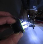
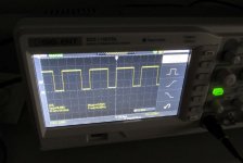
Carrying the investigation a step forward I scoped the signal at test point 13 while holding the led flasher directly in front of the photo transistors. Although the LEDs are quite bright it was necessary to align them and hold them very close to get a signal.

But I did: from the attached you can see a trace approximately 5V peak with a period of 166.6 ms. and a frequency of 6 Hz which the SM says is correct. Of course the 6 Hz is the frequency of the flasher, not the spindle or index sensor emitter, but it gives me some reassurance that I have isolated the problem.

Now to find the proper replacements...

-CH-
 

Attachments

  • TestingPhotoTs.jpg
    TestingPhotoTs.jpg
    51.6 KB · Views: 5
  • TP13Output.jpg
    TP13Output.jpg
    91.6 KB · Views: 5
Along the way, I wrote a "seek test" diagnostic--give it two cylinder numbers and it seeks to the second one, pauses 3 seconds and then seeks to the first and repeats until a key is pressed. Using a logic probe, you can see where things fail. If anyone needs it, I can post it.

Please do. Thanks,

-CH-
 
Okay, just entering "seektest" at a DOS prompt should provide a syntax summary. See "config.txt" for explicitly specifying drive configuration.
 

Attachments

  • seektest.zip
    13.7 KB · Views: 4
Back
Top