Mike Brixius
Experienced Member
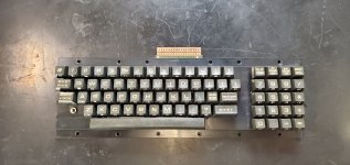
One more quick question. My keyboard has a 5x4 key numeric keypad and the matrix in the manual is 3x4 with a double wide 0 key. Is the matrix the same electrically on the different layout?
Mike
Mike
Disregard this. I finally found the matrix for the graphics keyboard. It looks to me like the 74ls145 binary to bcd decoder is bad. The variances on the matrix make no sense. The keys all produce consistent results but they don't follow any logic for a bit or two being stuck or a key code having a bit off. I decided to scope the 74145 and pin 7 looks like it's off. It rises to 4ish volts then drops to 3 over a succinct second or two...One more quick question. My keyboard has a 5x4 key numeric keypad and the matrix in the manual is 3x4 with a double wide 0 key. Is the matrix the same electrically on the different layout?
Mike
This device is tricky to test because it is an open collector output. In order to rest it, you require a 10k (or so) pull-up resistor to +5V on the pin you are measuring.Disregard this. I finally found the matrix for the graphics keyboard. It looks to me like the 74ls145 binary to bcd decoder is bad. The variances on the matrix make no sense. The keys all produce consistent results but they don't follow any logic for a bit or two being stuck or a key code having a bit off. I decided to scope the 74145 and pin 7 looks like it's off. It rises to 4ish volts then drops to 3 over a succinct second or two...
I'll find out in a few days when a replacement arrives
Mike
I had to do a refresher on open collector. You are right, it is fine. In fact it seems my issue is that I burned the wrong Edit ROM. I have found multiple things online on the keyboards and some call mine a graphics keyboard and others a business keyboard.This device is tricky to test because it is an open collector output. In order to rest it, you require a 10k (or so) pull-up resistor to +5V on the pin you are measuring.
This has caught a few people out before!
Dave


oh that is wicked expensiveThe Fluke high voltage probe I have is the model 80k-40. I bought it from RS Components, but it is a very very expensive item:
You would be better off to buy one of the eBay probes I cited.
I had (and lost) one of thoseoh that is wicked expensive