• Please review our updated Terms and Rules here

Straight-8 Type 183 Memory Extension question

antiquekid3

Veteran Member
Joined
Nov 10, 2009
Messages
855
Location
Alabama
I was reviewing the F-87 print set in hopes to learn more about the Straight-8's memory extension to see the likelihood of recreating it (and the Type 184 memory modules) for those of us with 4k Straight-8s.

In the print set, PD02/MD35 pin H ends up driving ENABLE FIELD 0. I assumed this might have been for enabling field 0 with no memory extension.
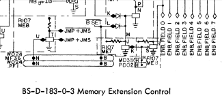
Screenshot_20240615-145621.png

But then I looked at the signal on the line...
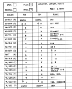
Screenshot_20240615-145250.png

To my surprise, it's OPR, which is asserted during an operate instruction.

That makes very little sense to both Vince and myself. What about field 0 should have a dependence on OPR?

Perusing the 183 description as well as Operate's description did not suggest anything obvious to me. Maybe I missed something.
 
A queston just occurred to me...were 680 terminal controllers used with straight-8? I seem to recall the terminal controllers UART implementation doing DMA, while also using the OPR mechanism to do a rotate on the data. (That was something I was looking at while trying to understand the history of the M220 modules in the 8/I.)
 
It does look like the Type 681 was used with the Straight-8. Still not sure I can understand the implication of OPR driving Field 0 enable all the time. Sure seems interesting...
 
If it's like I remember, there is a set of bytes being assembled in memory. As each bit comes in, a data break RMW is done to get the byte, rotate it (with carry-in or not), and rewrite it. When bytes are fully assembled, interrupts are generated, and the interrupt service picks up the assembled bytes. Similarly for output. Possibly the gates you are looking at are a support kludge to force field 0 for those data breaks. But really it seems more like the more proper thing would be for the terminal controller to set up address_extend[1:3] so the break decoder at mc3. would do the right thing.

Unless, somehow opr inhibits b_set.
 
I don't have a way to make F-87 text searchable right now, but it would be interesting to see what mentions of slot ME8 exist.
 
I did manage to pull together a list of the signals that I think were meant to be routed to the 184 memories. Looks very similar to the MM8/I bus, from what I can see, except that it's got both polarities for MA, and the field select is pre-decoded. I'm guessing that BMB was picked up from the Negibus slots?

I imagine that folks would just populate the relevant slots to assemble the 183 memory controller?
 
I imagine that folks would just populate the relevant slots to assemble the 183 memory controller?
That would be my assessment. I didn't know about the field 0 select Kyle mentioned so it might be that you would have to remove the card that originally drives that? Not at home so I can't just go look. It could also be that when 183 is installed a wire would be removed from the backplane. I can't imagine that adding a 183 and 184 to a machine would have been done by anyone but field service personal.
 
20 cards in MC through MF, 1 to 5, plus 7 more in ME/MF, 6 to 9, plus 15 more in MA through MD, 31 to 35. So 42 cards total, plus presumably 9 paddles for cables.

MD35 (a processor/memory chassis cable) is asterisked as a Type 183 only slot, but its mate, PD02, is not.

I'm assuming as Vince mentions that BMB comes from the I/O connectors (I think Doug mentioned this elsewhere as well), but the two I/O connectors with BAC (and other signals) are not necessary—BT1 is duplicated for the memory connector.
 
Well dangit. Single height module PCBs (without gold fingers) cost about $5 bare (in qty 5). Assuming we could get them assembled for us at $10, that's still in the $400-$500 range. That's a couple orders of magnitude more $$ than the CPLD to do the same thing.
 
Also there are at least 2 different memory backplanes. I have the newer one that was changed sometime in 1966 or early in 1967. The RICM machine is the earlier chassis. It would be nice to know what serial number this changed. SN 1173 and the two at System Source are the new chassis (I think both of them are SN in the 1200's). Now Kyle needs to look at his 8. I don't know all the changes but I do know that they reworked the shift register on the console port to not use an R405 as the clock for the newer machines. Most of the boards are in the same locations. It may be that the memory portion was unchanged.
 
Well dangit. Single height module PCBs (without gold fingers) cost about $5 bare (in qty 5). Assuming we could get them assembled for us at $10, that's still in the $400-$500 range. That's a couple orders of magnitude more $$ than the CPLD to do the same thing.
Yeah, most likely this can't be done any cheaper because you have to plug into a lot of those slots or you get to re-wire the backplane.

How many different types of cards and how many of each? Some boards might get a larger quantity price break.

It might not be technically that difficult, but it won't be cheap either. TTL makes the later machines a lot easier to deal with.
 
How many different types of cards and how many of each? Some boards might get a larger quantity price break.
I count 48 boards total, of 14 types, and counts of 1(2), 2(6), 3(3), 6(1), 7(1), and 12(1). (That counts the connector cards, but presumably some module-sized PCB or other will go into those slots.)
It might not be technically that difficult, but it won't be cheap either. TTL makes the later machines a lot easier to deal with.
What I was imagining was having JLC build them out of SMT components for us. That's relatively inexpensive, and also saves a boat-load (so many discretes!) of hand soldering.
 
Back
Top