• Please review our updated Terms and Rules here

The beginnings of my 4004 project

alank2

Veteran Member
Joined
Aug 3, 2016
Messages
2,264
Location
USA
If anyone wants to look over my start to some 4004 emulation, I've attached a zip of what I've been working on the last few nights. I've tested most of the opcodes, but not all of them yet. One thing I'm still considering changing about it is that I am storing a lot of nibbles in unsigned char which is a bit wasteful, but I'm trying to balance that against the performance loss of extracting and packing nibbles into bytes. I may try that and see how it does.

Where I want this project to go is first I plan on making a console application for it (WIN32), but I should be easily able to adapt it to DOS and CP/M as well. I've been wanting to make a control panel type CPU emulation project for awhile, but it is always the input side of things (switches, keys, etc.) that makes the UI unwieldy on a hardware board and just not quite what I'm looking for. Then I had the idea of what about making a smaller mini hardware board that has blinky lights for output, but not a real control panel. Instead it will be controlled through a serial port that has a monitor/debug type interface. Maybe that would be the best of both worlds. So, my first plan is console applications, then my second plan is to migrate them to an AVR based board with some LED's. The control/monitor is external to the emulation, not running inside the emulated CPU.

Here is what I have so far for the monitor interface:

Code:
A [address]            Assemble
B [breakpoint] [-breakpoint]    Breakpoints
C range target            Copy
D [address]            Dump
E [address]            Enter
F range data            Fill
G [address]            Go
I [=address] [qty]        Step into
K range target            Compare
LI <range>            Load intel hex
LX <range>            Load xmodem
LF <range> <file>        Load file
M [key]                Monitor break key
O [=address] qty        Step over
P [on|off]            Performance update (displayed every 10 seconds)
Q                Quit
R [assignment] [assignment]    Registers
SI <range>            Save intel hex
SX <range>            Save xmodem
SF <range> <file>        Save file
T [speed|off]            Throttle (speed is decimal cycles per second)
U [address]            Unassemble
X                Address spaces
Z range data             Search

The assemble function won't be a real assembler, but like how DOS DEBUG does it where you can assemble instructions on the fly, but there won't be any labels. I'd really like to be able to make it an environment where, like BASIC, one could sit there with it and assemble instructions to build a test program and step them to see how they work. The registers command would show during those steps like this:

R0=F R1=0 R2=F R3=0 R4=F R5=0 R6=F R7=0 R8=F R9=0 RA=F RB=0
RC=F RD=0 RE=F RF=0 S1=000 S2=000 S3=000 ACC=F DCL=7 SRC=FF NC
PC=000 1234 JUN 123

Not all commands would be present, Q/LF would be for a console program (WIN32/DOS/CPM) only, and LX would be for AVR only. Everything would be in hex except the T/throttle command.

One of the challenges with the 4004 was that it has different address spaces, so if you use the dump command for example, you can let it pick the last one, or you could specify one like "d pgm:0" to dump program memory starting at address 0. I'm thinking about these address spaces so far. This is 16x 4001 ROM's and 32x 4002 RAM's.

pgm: 0-FFF bytes program memory
pgmi: 0-F nibbles program memory input port
pgmo: 0-F nibbles program memory output port
data: 0-7FF nibbles data memory
datao: 0-1F nibbles data memory output port
stat: 0-1FF nibbles status memory

I'm probably biting off more than I can chew; I tend to do that with projects, but ultimately my test application for this would be to see if I can write an Enigma M4 machine emulator that runs on it. One thing I need for that is a serial interface accessible inside the 4004 emulation layer, and my plan so far on that is to use I/O ports. One 4 bit output port, one 4 bit input port, and then two control lines (1 bit input, 1 bit output). Using this the 4004 can communicate outside of its emulation to the AVR which can then handle the UART, etc. Theoretically an AVR could be also made to be an I/O processor for a real 4004 that works the same way.
 

Attachments

  • i4004.zip
    2.7 KB · Views: 3
The SIM4-01 just bit bangs the serial data with delays.
If you can also emulate a 4265 chip to talk to the 8 bit world. Then you could just use any UART you like.
Do note the 4004 doesn't have an interrupt so you either need to hand shake or go to a 4040 chip instead.
 
Thanks Dwight. I hadn't seen the 4265 yet. Do you know where a good complete datasheet for it is? I tried searching and couldn't find one.

I plan on using 10 I/O's to communicate virtually from inside the 4004 to the emulation layer (which can handle serial in/out or console i/o). I saw that the 4289 uses ROM ports 14/15, so for the emulation I'm thinking of using 11/12/13 where 11 pin 0=req output, 11 pin1=ack input, 12=4 pins output, 13=4 pins input. The 4004 would then set a nibble on ROM 12's port, set req, then the AVR or emulation would set what it wants to send to the 4004 on ROM 13's port, and set ack. Then the 4004 side would capture ROM 13's port (if needed) and clear req, and finally the AVR or emulation would clear ack. This would be a SPI like send to receive type of thing, but with nibbles. The 4004 could first send a command nibble, so 0000 could be get serial status (is a byte ready, is the tx buffer available), and then 0001 could receive byte, 0010 could be send byte, etc. I think this would work in emulation and also in the real with an AVR which would be cool. The obvious thing here is makingt this work in emulation, but I think an AVR could easily be made that would do the same thing for a real 4004.

For example, to receive a byte from a serial port, 3 transfers would be required (it would have had to have already had another transfer to know a byte is available). It could be <send>0001 (command to get byte from serial). What it receives from that send might be the high nibble, then it would send a dummy value like 0000 so that it can receive the second low nibble. Should low be transferred before high? Maybe, I'm not sure about endianness to use there just yet.

To send a byte (again implying it queried status to know it can transmit) could be a command 0010, ignore what is sent back, send high nibble, ignore what is sent back, send low nibble, ignore what is sent back.

All this is very much ahead of where I am now. I finished up the code that throttles emulation to a specified speed, so next I'm working on the dumping/editing of the 4004's various address spaces. After that stepping/execution/registers. Once I have that I'll try for loading data in intel hex so I can use a 4004 assembler and load programs to start testing them. Then I need to get the assemble/unassemble working. Then a 4004 program that can communicate using the above method in emulation to tx/rx bytes., then I can finally work on some of the Enigma M4 code.
 
It on the web someplace, I just don't recall where. It might be more related to 4040 stuff than 4004.

You're emulation should as a normal thing, keep track of clock cycles and know what speed it was running at relative to a realtime clock, if you wanted to connect to the real world. This all falls under what I call instrumenting your emulation. It is connecting all the things that might interest a user or outside hardware. Otherwise it is just something that runs code but has no function. Things like keypads, displays and in this case serial I/O are all part of instrumenting it.
If you need real time, you need that as part of what you are doing or someway to connect to real time.
My simulator code counts cycles and expects action to synchronize to outside time.
Dwight
 
I should add the the biggest single mistake most make is to think the 4004 can do 4 calls and returns. The PC counter is actually one of the stack elements. This is important if you want to emulate the assembler code that runs on the 4004. It uses this to abort the current stack to start new code.
Tricky isn't it.
Code written for the 4004 won't necessarily run on a 4040 but most code will. The stack depth is the main difference.
Dwight
 
>This is important if you want to emulate the assembler code that runs on the 4004.

What code is out there?

>It uses this to abort the current stack to start new code.

I implemented the PC separately from the stack so far, but are you saying it needs to be part of the array - I'll have to think if it would work the same way either way. I'd rather not have to constantly index the pc in an array if I can avoid it.

Code:
struct i4004
  {
    //internal registers and state
    unsigned char acc, carry, test, reg[16], dcl, src, sp;
    unsigned short pc, stack[3], wpm, wpmnibble;

    //program memory and ports (16x 4001)
    unsigned char pgm[4096];
    unsigned char pgmi[16];
    unsigned char pgmo[16];

    //data, status memory and port (32x 4002)
    unsigned char data[2048];
    unsigned char status[512];
    unsigned char datao[32];

    //control
    unsigned char nobrk, runmode, reportspeed;
    unsigned short brk[MAX_BREAKPOINTS];
    unsigned long icycles, speed;
  };

Code:
          case 0x50: case 0x51: case 0x52: case 0x53: case 0x54: case 0x55: case 0x56: case 0x57:
          case 0x58: case 0x59: case 0x5a: case 0x5b: case 0x5c: case 0x5d: case 0x5e: case 0x5f:
            //jms
            c2=APtr->pgm[APtr->pc++];
            if (APtr->pc>=0x1000)
              APtr->pc&=0xfff;
            APtr->icycles++;
            APtr->stack[APtr->sp++]=APtr->pc;
            if (APtr->sp>=3)
              APtr->sp=0;
            APtr->pc=(unsigned short)(((c1&0xf)<<8) | c2);
            break;

          case 0xc0: case 0xc1: case 0xc2: case 0xc3: case 0xc4: case 0xc5: case 0xc6: case 0xc7:
          case 0xc8: case 0xc9: case 0xca: case 0xcb: case 0xcc: case 0xcd: case 0xce: case 0xcf:
            //bbl
            APtr->sp--;
            if (APtr->sp>=3)
              APtr->sp=2;
            APtr->pc=APtr->stack[APtr->sp];
            APtr->acc=(unsigned short)(c1&0xf);
            break;
 
>It uses this to abort the current stack to start new code.

I should have also asked; if you have an example of this that would be awesome.
 
>It uses this to abort the current stack to start new code.

Still wrapping my mind around this.

How does it use it?

If there are 4 entries, and PC is simply the one being pointed to, and 0 is indexed, then 0 begins to advance.

when a JMS instruction is processed, the PC is first incremented to the next instruction, then the sp index is incremented, then that current entry is set to the JMS address.

when a BBL instruction is processed, i suspect the current PC is still incremented (instruction following BBL), but then the sp index is decremented leaving the PC back at the last JMS+2.

If BBL is then used too many times, will it go back to a PC that was never pushed with a JMS?

at loop1's jms, index 0 (pc) will point to "bbl 3", but then the index will move to 1
at loop2's jms, index 1 (pc) will point to "bbl 2", but then the index will move to 2
at loop3's jms, index 2 (pc) will point to "bbl 1", but then the index will move to 3
at loop4's bbl 0, index 3 (pc) will point to "loop 5", but then the index will move back to 2, 1, 0 where it will finally be at "bbl 3". What does it hit then? loop 5?

the emulator at e4004.szyc.org does not work that way for sure.

Code:
loop1
  jms loop2
  bbl 3

loop2
  jms loop3
  bbl 2

loop3
  jms loop4
  bbl 1

loop4
  bbl 0

loop5
  jun loop5

Code:
pass 1: done
pass 2

0000: LOOP1  
0000:        JMS LOOP2       50 03
0002:        BBL $03         C3
0003: LOOP2  
0003:        JMS LOOP3       50 06
0005:        BBL $02         C2
0006: LOOP3  
0006:        JMS LOOP4       50 09
0008:        BBL $01         C1
0009: LOOP4  
0009:        BBL $00         C0
000A: LOOP5  
000A:        JUN LOOP5       40 0A
done.
 
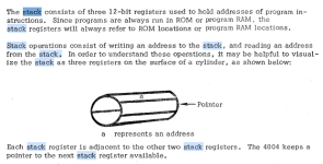
Also, the manual MCS-4_Assembly_Language_Programming_Manual_Dec73.pdf in section 2-4 does not show the stack as a 4 position item at all, but a 3 position cylinder.
 
Someplace in the manual or in other docments about the design it mentions that the stack has 4 register and that one of them is the current PC. It is used by Tom Pitman's code. ( available on bitsavers. http://www.bitsavers.org/components/intel/MCS4/Pittman_MCS4_Assembler.zip This is the assembler described in the manual )
How you implement this is up to you if you like it or don't or don't believe me. I'll see if I can find where the description of the PC can be found.
I've used his assembler in my simulator and it works, so there is some code out there.
There is also some code that NTSB has that was used to track delay times from satellites. The code I implemented in hardware was from Monterey PNG school. It was done by a couple of students of Gary Kildall. The pdf was originally printed on something like a ASR33 with ruts in the platen. Part of print on some Columbus are missing. The code and hardware is used to track the positions of ships nearby of specific shore features. I have that code working on real hardware I made myself, based on the description and the software code. It is describe in a 4004 post on this forum.
Dwight
 
I know you'll just say I'm wrong but you can look at yourself:
frame 17 or page 13, at the top of the page. It clearly shows the JMS #4 over writing Return Address #1.
The text notes that the "If a fourth JMS occurs, the deepest return address (the first one stored) is lost."
The diagram shows a "blank spot" but the address is not blank, it is the address after the fourth JMS just like
any other JMS but the first address is lost replace with the return of the fourth JMS.
Like I said, Tom uses this feature to change from the first pass of his assembler to the second pass.
So, it is not 3 rolling registers, it is 4 registers, like I said, with one register being the current PC. It is truly
implemented that way in hardware if you care to look at the chip diagram ( on the web someplace ).
As a note Tom's code can not be run on the 4040 without some modification to handle this feature.
I'd be curious where you saw the 3 rolling stack?
Dwight
 
I can see on page 27, that is also says the deepest return address is lost but doesn't mention that the return address of the 4th JMS overwrites the deepest one. This is a clear omission as it is what the real silicon does. I don't know why they didn't state it. It would have been difficult for the hardware to do anything else, special, with the 4th JMS.
Anyway, not a 3 rolling stack, like the data stack on a HP calculator, and if you'd like to run the assembler your emulator has to match what the silicon does.
The assembler assume it is on the SIM4-01 connected to a ASR33 with the handshake relay described in the manual. Without keeping track of clock cycles, you can not, properly, emulate this but you can trap the calls, to the serial in and out, and avoid needing to keep track of cycles.
In mine, I keep track of clock cycles but that is up to you. I find it handy.
Dwight
 
I've got faith in you Dwight - I appreciate your knowledge and feedback!

I did find the Return Address examples you mentioned last night as well, so it looks like maybe they evolved from the cylinder below into something more accurate.

I need to fully read through all 3 of your emails here, but the 3 rolling stack I saw in this manual under 2.4:
MCS-4_Assembly_Language_Programming_Manual_Dec73.pdf
1704814707657.png

My code above was a test to push values into the stack and then call BBL 4 times to see what it would do - the first 3 we know what it will do, but the 4th BBL? What address will the PC get? What will be the next instruction?
 
A BBL after a 4th JMS The next BBL will go back the to next instruction after the 4th JMS. This at first looks like any JMS/BBL instruction.
There is no special hardware to handle any of this. There is a two bit pointer for the registers.
It either increments of decrements and wraps around. It points to the current PC. To JMS, it changes the pointer in one direction, after getting the start of the subroutine, and a BBL it goes the other direction ignoring the old PC.
Each JMS has no knowledge of how many JMS's have preceded it. It does exactly the same thing.
Each BBL does exactly the same thing as any other BBL. It has no knowledge of how many BBL's before it.
There is no special knowledge about when it will overwrites the first return. It is just the number of JMS's
There are 4 registers of which one is the current PC. This gives you 3 levels of nesting without getting lost.
This visual model works as long as you don't over do the stack depth. Then you have to go to the actual physical design.
It is actually 4 registers, with one being the current PC. The the JMS instruction is executed the PC is increment and reads the destination pointed to by the JMS instruction into the next register of the 4 register cylinder and move the current PC to be that register. The one that used to be the PC is now the address for the BBL instruction.
To properly emulate this action you need to indirectly access the PC and the location +or- from the PC register to get the location that has the return.
The direction roll the 4 bit registers is not important, the only thing is that it does require 4 locations.
To tell you the truth, I don't think, even think, set the pointer on power up since it isn't important where it starts. It is just 2 bits.Incrementing or decrementing the pointer for JMS and BBL is only important that they are opposite, so pick what you like.
It is still best to fetch the PC through an indirect pointer, that is always update modulo 4 ( a nice 2 bit number ). Then you don't even have to think about what it is doing, it will always matches the silicon.
You can keep your three locations rolling register but then you need to do a modulo 3 instead of a simpler 2 bit number. ( 00, 01, 10, 11, 00, 01 and so on ). For the 3 locations it is ( 00, 01, 10, 00, 01 and so on ). Easy to code but clumsy to execute.

Dwight
 
The reason I thought it might end up at instruction loop5 after executing the BBL $03 at address 2 is because I wondered if it would run into the PC (stack[3]) that was left at 00A

Code:
0000: LOOP1                                          ;lets say sp=0 (so the stack[0] is currently the PC)  
0000:        JMS LOOP2       50 03           ;pc/stack[0] will be 0002, then sp ++, new pc/stack[1]=0003
0002:        BBL $03         C3                   ;pc/stack[0] will be 0003, then sp--, new pc/stack[3]=000a
0003: LOOP2  
0003:        JMS LOOP3       50 06           ;pc/stack[1] will be 0005, then sp ++, new pc/stack[2]=0006
0005:        BBL $02         C2                   ;pc/stack[1] will be 0006, then sp--, new pc/stack[0]=0002
0006: LOOP3  
0006:        JMS LOOP4       50 09           ;pc/stack[2] will be 0008, then sp ++, new pc/stack[3]=0009
0008:        BBL $01         C1                   ;pc/stack[2] will be 0009, then sp--, new pc/stack[1]=0005
0009: LOOP4  
0009:        BBL $00         C0                   ;pc/stack[3] will be 000a, then sp--, new pc/stack[2] is 0008 (this should leave stack[3] at 000a I *think*)
000A: LOOP5  
000A:        JUN LOOP5       40 0A

I looked at the assembler code above, converted it to hex, and tried executing it on my emulator making it show the JMS/BBL instructions, but this is all it does before no more JMS/BBL commands. Maybe it is in a loop waiting for data.

Code:
000: jms (level 0 to 1) 05f
064: bbl (level 1 to 0) 002
104: jms (level 0 to 1) 2ba
2bc: jms (level 1 to 2) 1e0
1e0: jms (level 2 to 3) 05f
064: bbl (level 3 to 2) 1e2
3ff: bbl (level 2 to 1) 2be
07a: jms (level 1 to 2) 061
064: bbl (level 2 to 1) 07c

Can you point out in the assembler disassembly where it does the thing you mention - that way I can see what he is trying to do and how to make it work!

>I should note that it will not
>run on a 4040 as the code takes advantage of the limited stack. He intentionally
>over flows the stack at one point to redirect the code to do different things. I
>believe it was to change the mode from first pass to second pass.
 
The reason I thought it might end up at instruction loop5 after executing the BBL $03 at address 2 is because I wondered if it would run into the PC (stack[3]) that was left at 00A

Code:
0000: LOOP1                                          ;lets say sp=0 (so the stack[0] is currently the PC) 
0000:        JMS LOOP2       50 03           ;pc/stack[0] will be 0002, then sp ++, new pc/stack[1]=0003
0002:        BBL $03         C3                   ;pc/stack[0] will be 0003, then sp--, new pc/stack[3]=000a
0003: LOOP2 
0003:        JMS LOOP3       50 06           ;pc/stack[1] will be 0005, then sp ++, new pc/stack[2]=0006
0005:        BBL $02         C2                   ;pc/stack[1] will be 0006, then sp--, new pc/stack[0]=0002
0006: LOOP3 
0006:        JMS LOOP4       50 09           ;pc/stack[2] will be 0008, then sp ++, new pc/stack[3]=0009
0008:        BBL $01         C1                   ;pc/stack[2] will be 0009, then sp--, new pc/stack[1]=0005
0009: LOOP4 
0009:        BBL $00         C0                   ;pc/stack[3] will be 000a, then sp--, new pc/stack[2] is 0008 (this should leave stack[3] at 000a I *think*)
000A: LOOP5 
000A:        JUN LOOP5       40 0A

I looked at the assembler code above, converted it to hex, and tried executing it on my emulator making it show the JMS/BBL instructions, but this is all it does before no more JMS/BBL commands. Maybe it is in a loop waiting for data.

Code:
000: jms (level 0 to 1) 05f
064: bbl (level 1 to 0) 002
104: jms (level 0 to 1) 2ba
2bc: jms (level 1 to 2) 1e0
1e0: jms (level 2 to 3) 05f
064: bbl (level 3 to 2) 1e2
3ff: bbl (level 2 to 1) 2be
07a: jms (level 1 to 2) 061
064: bbl (level 2 to 1) 07c

Can you point out in the assembler disassembly where it does the thing you mention - that way I can see what he is trying to do and how to make it work!

>I should note that it will not
>run on a 4040 as the code takes advantage of the limited stack. He intentionally
>over flows the stack at one point to redirect the code to do different things. I
>believe it was to change the mode from first pass to second pass.
There may be jumps that change the depth of the stack. My statement was based on statements from Tom himself. I don't know where I saw such stuff from him. He has since moved on and is no longer interested in this early work, that last time I communicated with him ( maybe 10 years ago ).
I believe there is a point where it detects the end of the first pass and it does a conditional jump to the extra level of JMS.
It has been some time since I followed the code.
Dwight
 
I got you Dwight - I'll take a look at the code and see if I can figure out anything. In any case, I'll go with the 4 array table where the PC is part of it I appreciate it!
 
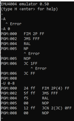
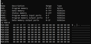
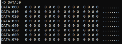
I have a few of the monitor features working now. Assemble, Dump, Help, Quit, Unassemble:

Next commands to implement are Enter, then Registers, then Go/StepInto/StepOver/Breakpoints...

1705635711780.png

1705635756957.png


1705635777958.png

1705635852685.png
 
It is coming along; a lot of work has been done this weekend!

Commands implemented are: assemble, dump, enter, help, step into, initialize cpu, step over, program counter, quit, registers, unassemble, display pause, and address spaces.

Notably what isn't done yet is breakpoints, go, throttle, plus others.

But you can assemble and step instructions! You can view and edit memory or any internals of the CPU like registers, accumulator, etc.

No warranty provided; use at own risk.

There are 3 programs in the ZIP file - one for CP/M (should run on 8080 CPU's), MS-DOS, or WIN32 console.

Give it a try and let me know if you find any issues or bugs thus far.


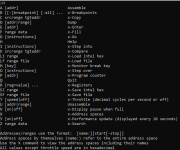
Type H for help - here it is - items with // are not implemented yet:
Code:
A [addr]                      Assemble
B [[-]breakpoint] [-all] ...    //Breakpoints
C srcrange tgtaddr              //Copy
D [addr|range]                Dump
E [addr]                      Enter
F range data                    //Fill
G                               //Go
H                             Help
I [instructions]              Step into
K srcrange tgtaddr              //Compare
LI range                        //Load intel hex
LF range file                   //Load file
M [key]                         //Monitor break key
N                             Initialize CPU
O [instructions]              Step over
P [addr]                      Program counter
Q                             Quit
R [reg=value] ...             Registers
SI range                        //Save intel hex
SX range                        //Save xmodem
SF range file                   //Save file
T [speed|off]                   //Throttle (decimal cycles per second or off)
U [addr|range]                Unassemble
V [on|off]                    Display pause when full
X                             Address spaces
Y [on|off]                      //Display performance update every 10 seconds
Z range data                    //Search

Addresses/ranges use the format:  [name:][start[-stop]]
Address spaces by themselves (name:) refer to the entire address space
Use the X command to view the address spaces including their names
All values except throttle speed are in hexadecimal
 

Attachments

  • emu4004_0.50.zip
    78.2 KB · Views: 2
Back
Top