• Please review our updated Terms and Rules here

The infamous RD53 / Micropolis 1325

Lou - N2MIY

Veteran Member
Joined
Apr 1, 2008
Messages
1,306
Location
Albuquerque NM / Potomac MD
I have started another impossible project. I got a bad RD53 (Micropolis 1325) from fellow forums fan, Marty.

I have scoured the internet for all I could learn about this most infamous of MFM hard disks. They usually have at least one of two common problems - stuck heads or spindle motor problems. The one I have has spindle motor problems.

Of course, no print set has ever turned up. However, the dec technical manual was photographed from fiche, which I have downloaded and devoured.

The spindle motor is a three pole brushless dc motor. Commutation synchronization is provided by three hall effect sensors. There are eight permanent magnets mounted inside a ring (the rotor) screwed to the spindle. Each pole is driven by its own TIP125 darlington pair. Power comes from the 12V supply, and all poles power goes through a low value resistor used for current sensing (and limitation circuit). The drive is unipolar and there is only one pole powered at a time (by design).

I reverse engineered most of the motor driver circuit from the board traces. I repaired one broken pole driver and another that was used for the brake solenoid. The electronics all appear to be working as they should. But, the motor will still not come up to full speed (3600 RPM)!!!

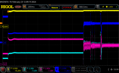
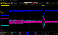
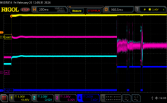
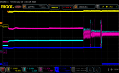
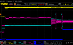
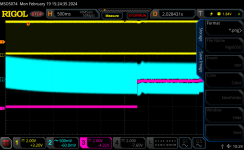
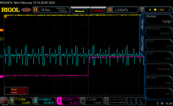
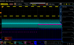
The drivers are driving hard, and the synchronization with the rotor looks pretty good on the scope. But there are two weird things.

1.) one of the sensors seems late by a small angular amount
2.) the sensor duty cycle is weird. The "on" time is 2/3 of the "off" time. In the diagram in the tech manual, the duty cycle is 50/50 (as it is in all other examples of hall effect commutation on the internet). I tried removing the rotor and shimming it slightly so that it was about 0.010" farther from the sensors. No change.

However, the actual driving of the poles looks good on the scope. The current limiting circuit only kicks in during starting. I can bypass it and spin up faster, but either way, it only goes to 3/4 speed and stays there. The rotor is very well balanced.

If I use an adjustable 12-15V supply, I can spin the motor faster. I only went to 12.6V though, because there is a 5V reference generated with a zener regulator from the 12V source and the zener was getting hot. It does regulate properly though. I think I'd need about 16V to actually get to full speed.

I've seen youtube spinups of the RD53, and they get up much faster than mine.

I think one of two things is the problem:

1.) There is more spindle bearing friction than there should be. It feels ok though and doesn't make any noise?
2.) I'm no physicist, but can the permanent magnets lose their magnetism? Googling that made me think it's possible, but why does the youtube guy's drive still work? It would explain the loss of torque and strange hall effect sensor duty cycle.....

So, if you have an RD53 doorstop that you're willing to donate to science, let me know. I want to put your magnet ring on my drive. I also want to compare how stiff your spindle bearings are.

Any comments or insights are welcome. Maybe we can make some progress toward salvaging some of these doorstops.

Lou
 
Pat,

I should sketch it neatly, since what I have are bits and pieces when I was intersted in different sections. In words I can describe it pretty easily though.

The hall effect sensors are Sprague UGN3040 three terminal devices with on-board regulators (insensitive to supply voltage). Open collector outputs. Pulled up to +5 with resistors on the board. They feed the three least significant input bits of a 7445 BCD to decimal converter. It's really clever use of the 7445. The fourth (and most significant bit) goes to the output of a comparator that monitors the motor current (voltage drop across a low value resistor) The outputs of the 7445 (open collector) drive the bases of the PNP darlington pairs by pulling down the middle of a voltage divider. (Motor windings are wye connected by the way.) The clever part of using the 7445, is that the 0,1, and 5 decimal outputs are wire-ored together and drive one pole, the 2,3,and 7 wire-ored and drive another pole, and 4 and 6 are wire-ored and drive the remaining pole. This provides the correct logic to drive the right pole when the right combination of hall sensors is detecting. When the most significant input bit is set, the output is 8 or 9, which kills the 0 through 7 outputs, preventing pole driving when the current is too high.

Speed control is provided by the main controller board. It uses bang-bang control. It's fed the pulses from one of the three hall effect sensors and counts frequency. If the motor is overspeed, it stops pole driving through the overcurrent comparator. If underspeed, it lets things keep trucking. There's deadband of course with bang-bang control, but that's how they designed this thing.

Should I still draw up a sketch of the schematic?

Lou
 
Appreciate this is a very old thread, but hoping somebody here can answer.
I'm trying to diagnose why my Micropolis HD spins up but never switches over to servo data.
I can see the BCD->decimal clock over and a trace of the Interrupt input on the main board microprocessor shows a good trace on Pin 13

Q: What frequency is needed to trigger switching over to servo data? You can see it gets to ~240 Hz. Is that too low? It occasionally gets to 250Hz..

What should I be measuring? If the interrupt is from 1 of 3 hall effect sensors, the pulses are being generated at 1 pulse / revolution, right?
But a 3600rpm disk speed should be a 60Hz pulse..

Any help much appreciated.

S3-2.jpg
 
Last edited:
Looking at page 6 of the 1325 schematics it shows the 4-bit input to the BCD and the 0-9 decimal outputs being tied together in a cunning way as explained by Lou earlier in the thread.
All 3 lower input bits from the Hall effect sensors look sensible:

a.jpegb.jpegc.jpeg
Bit 3 of the BCD input is from the comparator that when high makes the decimal output >= 8 so the phase drivers are disabled (slowing the rotation)
When low, the drive gets faster and faster (as I understand it).
What I see is, as the disk sounds like its getting to its top speed, the comparator kicks in so that the continuous pulses on the decimal outputs becomes interrupted. For example this is decimal output "3" from the BCD->decimal convertor:

dig3.jpeg

Before "top speed" its just a continuous stream of those pulses.

And Bit 3 of the BCD input looks like this at "top speed" - ~50% high and ~50% fast pulses.
d.jpg

Q: can I just pull Bit 3 low to force it to go faster and faster? Will it explode?

Anyway, if any wise old peeps out there recognize these symtoms, would love to hear your thoughts.

Adam
 
Made some measurements. Trace 1 is pin 13 of the processor. It starts around 200 Hz and gets to 239 Hz when trace 3 switches. Triggered scope when sounded like getting close to speed.
Trace 2 is test point 4 servo data.
Trace 3 is U11 spindle control enable. Shortly after that signal changes I can hear the heads move.

Second is zoomed in on when trace 3 switches.

The third I added trace 4 BCD counter pin 12

When drive is normally operating Trace 1 is 240.07 Hz.
 

Attachments

  • RigolDS0.png
    RigolDS0.png
    99.4 KB · Views: 6
  • RigolDS1.png
    RigolDS1.png
    85.7 KB · Views: 6
  • RigolDS2.png
    RigolDS2.png
    168.1 KB · Views: 7
And U11 spindle control enable (pin 35) goes high when the disk sounds up to full speed too..
It feels like everything I look at gives expected results. But the heads never try and seek track 0.
 
[Been honing in on the motor board since everything I look at on the control board looks fine-ish.]

I've had the scope on various parts of the power amp / power amp enable motor board circuitry and I'm getting signals. Vr is a steady 5v, paen / pa switch once disk gets up to speed.
The only thing I found - that I dont understand because I dont known what VC1 and VC2 are - VC1 is around 10v, VC2 is near zero. Is that expected?

vc12.jpg

Screenshot 2024-02-22 at 17.46.20.jpg
 
Lastly, the 2.4v Zener diode (VR1) shows a reverse-biased voltage of 1.32v (forward is 0.7v). Is that right?
Apologies if these are dumbass questions, I am soooo way out of my wheelhouse on this stuff :)
 
Is your drive acting like this?
Is the head lock solenoid actuating?
No, I dont hear (or see) any movement of the heads.

I tried nudging the solenoid with a chopstick and sometimes it seeks to the middle of the disk, then spins down and parks the heads.
So it appears it can mechanically move the heads, just doesn't get a signal to do so..
 
Lastly, the 2.4v Zener diode (VR1) shows a reverse-biased voltage of 1.32v (forward is 0.7v). Is that right?
In circuit I got similar values. The components around it affect the reading. If you measure with the drive powered you will see correct drop across it when its biased. Its not always biased.

I dont known what VC1 and VC2 are - VC1 is around 10v, VC2 is near zero. Is that expected?
VC1 and VC2 are driving the voice coil for moving the head. Force moving the head is proportional to current. Which direction heads move is based on which direction the current flows. These values should be driving the head hard against one of the stops. If that's all it does not good.

Page 24 of PDF is current amplifier for PA signal. PA is referenced to Vr. The difference drives the current amplifiers to drive VC1 and VC2 differentially. Voltage gain is close to unity. DS16 shows entire start oup sequence from PAEN going high. DS18 is zoomed in so you can see how PA generates VC1 and VC2 when its moving heads around. VC1 is cyan with same 0 reference as VC2. The farther PA is from Vr drives more current in to the voice coil with polarity controlled by if PA is above or below Vr. Voice coil resistance measured around 3.5 ohms.

The last 3 show the control voltages to DG211 U29 on PDF page 16 selecting which signal(s) drive PA.

Zip file is csv of DS16 waveform if you want to see the voltages. 25M points so may be a little unwieldy.

Vr is about 5.4 volts on my drive.

Lost servo/ to processor was high during this sequence.
 

Attachments

  • RigolDS16.png
    RigolDS16.png
    96.1 KB · Views: 4
  • RigolDS18.png
    RigolDS18.png
    143.5 KB · Views: 5
  • RigolDS18.png
    RigolDS18.png
    143.5 KB · Views: 5
  • RigolDS15.png
    RigolDS15.png
    89.9 KB · Views: 4
  • RigolDS13.png
    RigolDS13.png
    92.6 KB · Views: 4
  • RigolDS12.png
    RigolDS12.png
    97.7 KB · Views: 4
  • RigolDS0.csv.zip
    2.7 MB · Views: 1
Last edited:
[Thank you for all that. Really helpful]

On U8, I'm seeing High Velocity Range/ Pin3 start low and transition to high at full speed. Q: Does not the trailing slash indicate active low?

However, Velocity Enable/ Pin4 (& Compensator Reset) remain always low.
I'm presuming that disables page 16 showing generation of PA.
 
Last edited:
David G I think has experience with these drives. Maybe this link might help? He makes an MFM emulator board which is awesome. I have a few 1325's. I think one works fine.. the other has issues. I know one had problems and I had a spare board for it. I swapped out the board and whala! Aside from some bad sector reads on one particular head I could get data off of it. I think I still might have some spare boards. When I bought a bunch of machines they destroyed the hard drive and took out the platters and top shell but left the bottom metal and the board. Was going to throw them out but thank god I didn't.. I used it for the one I fixed.

 
David G I think has experience with these drives. Maybe this link might help? He makes an MFM emulator board which is awesome. I have a few 1325's. I think one works fine.. the other has issues. I know one had problems and I had a spare board for it. I swapped out the board and whala! Aside from some bad sector reads on one particular head I could get data off of it. I think I still might have some spare boards. When I bought a bunch of machines they destroyed the hard drive and took out the platters and top shell but left the bottom metal and the board. Was going to throw them out but thank god I didn't.. I used it for the one I fixed.


Oh David's MFM emu board is awesome - he's been posting in this thread. I'm using the mfm-emu board on the Tektronix 4404.

But it has niggled at me that I have 2 Micropolis 1304 from Tektronix4404s, both of which don't stay spun up and may have some of my software projects from long ago that has "sentimental value". With the help of peeps on this thread I have checked a bunch of things - it does feel like it "almost works" :)
 
Back
Top