Another, less hand-wavy way to think about it is that the design voltage for the indicators in a real 8/i is 15V unregulated. So, anywhere from maybe 20V during power up, to perhaps 12V if you tried to run all the bulbs, full on.
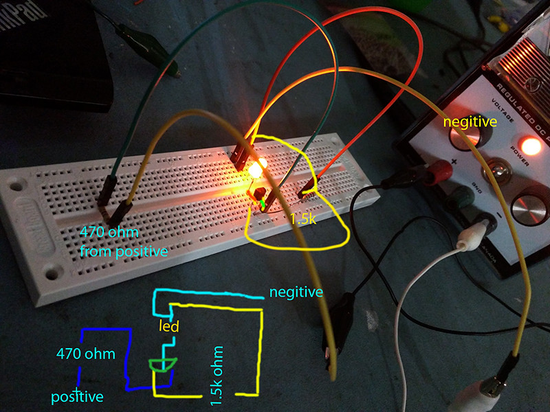
The same current runs through the transistor, the LED, and the resistor, since they are connected in series, and the voltage is divided up between them.
A typical inexpensive amber LED has a design voltage of about 2.1V. That means that, give or take just a little, the voltage across it will be about that.
The saturation voltage of a PN2222 transistor is about 0.3V, measured from emitter to collector while 15 mA is supplied from base to emitter. Adding those together, we get a little shy of 2.5V of relatively fixed voltage drop.
Subtracting that from the nominal 15V, we see that we want our resistor to drop about 12.5V.
Our typical amber LED wants 20 mA, so to get 12.5V dropped across the resistor would be 625 ohms. This is because resistors obey Ohm's law, requiring voltage to be the product of current and resistance.
You've got 1500 ohms, so you'd drive that LED with 8.3 mA, or about 42% of full power. For the LED data sheet I'm looking at, that is still about 3000 mcd bright, and probably fine. (It's also enough to light an old school 10 mA LED, some of which didn't get all that bright.)
On the other hand, running from a 5V supply would give a current of about 2.5V/1500 ohms, or about 3.3 mA. That's about 1/6 brightness, and would likely seem rather dim.
Part of the reason for 1500 ohms in my drawing was that it was a pretty safe value. Until you get into "fry the components" values, it's mostly going to work, and adjusting the resistor value is really more about making the LED you bought perform the way you want your panel to look.
Vince

")