• Please review our updated Terms and Rules here

TRS-80 diagnostic/ICE card

For those who are interested or have already ordered a board from me. Here is a link to the latest version of the Arduino code.

https://drive.google.com/open?id=1y0C-DS4oTwp-Ijdf6OAoq0-NNrJEy_XE

I've added some new features and quite a few bug fixes to the original code. I believe the refresh timing bug in the original code has been fixed, however my model one has a fault which prevents me properly testing it.
It seems addresses in the range ?000h-?7FFh refresh fine but ?800h-?FFFh addresses lose coherency after a few seconds. The problem also occurs when not using the exerciser and the cpu is active as normal. I'm pretty certain the problem is caused by the 48k memory mod that is fitted. So if some of you guys that ordered aboard could test the refresh ability of the exerciser I'd greatly appreciate it.

David,

I soldered up the board back on the weekend. Then today my Mega FINALLY arrived. Put the image in, and hooked up to the EI connector (haven't ordered the header to go into the CPU socket). So . . . some things work, some don't. A brief overview:

TC
ROM 1 0000h - 0fffh : B078
ROM 2 1000h - 1fffh : DA45
ROM 3 2000h - 2fffh : 4006
ROM set identified as TRS-80 v1.31


TD works fine.

However none of the normal memory actions work, with or without refresh enabled:


R+
refresh on
MW3000 AA
MWR 3000: AA
MR3000
MRD 3000: FF

U3000-3010
Testing RAM range 3000 - 3010
Failed with pattern 00000001 at 3000
Failed with pattern 00000001 at 3001
Failed with pattern 00000001 at 3002
Failed with pattern 00000001 at 3003
Failed with pattern 00000001 at 3004
Failed with pattern 00000001 at 3005
Failed with pattern 00000001 at 3006
Failed with pattern 00000001 at 3007
Failed with pattern 00000001 at 3008
Failed with pattern 00000001 at 3009
Failed with pattern 00000001 at 300A
Failed with pattern 00000001 at 300B
Failed with pattern 00000001 at 300C
Failed with pattern 00000001 at 300D
Failed with pattern 00000001 at 300E
Failed with pattern 00000001 at 300F
Failed with pattern 00000001 at 3010
RAM test done.


Suggestions?

PJH


ARGH!

:blush::blush::blush:

How about I remember what the M1 memory map is. When I actually try a valid memory location, it all works.

MWR 3FF0: 30
MRD 3FF0: 30
MRD 3FF0: 30
MRD 3FF0: 30
MWR 4200: 33
MRD 4200: 33
Testing RAM range 4200 - 4210
RAM test done.


So all seems good so far.

PJH
 
There is no RAM in a model 1 at 3000h.
RAM starts at 4000h

Edit: I replied before I realised you put up a 2nd post.

You should find that everything works using the expansion connector. I originally decided to go with the expansion connector option due to limitations with the original software and the CPU socket connection. However I've since solved those timing issues in the software.
Everything should work using either connection, the only real difference is the expansion interface gains a little in convenience at the cost of not being able to test the buffers between the CPU and the rest of the system.
 
Last edited:

MWR 3FF0: 30
MRD 3FF0: 30
MRD 3FF0: 30
MRD 3FF0: 30
MWR 4200: 33
MRD 4200: 33
Testing RAM range 4200 - 4210
RAM test done.


So all seems good so far.

PJH

I've now tried it on my M1 with a 48K mod[1]. Tested writing to F000 - with refresh off ("R-") I saw the value start to decay after ~30 seconds or so. With refresh on ("R+") the value was still good after a few minutes - with a "U" test (UF100-F200) in there as well.

PJH

[1] In fact heavily modded. Started life as a L1 4K, now a L2 with 48K in the keyboard. Though the ROM check fails for this one:


TC
ROM 1 0000h - 0fffh : AE5D
ROM 2 1000h - 1fffh : DA84
ROM 3 2000h - 2fffh : 4002
Unknown or faulty ROM set
ROM set identified as LLLLLLLLLLLLLLLLLLLLLLLLLLLLLLLLLLLLLLLLLLLLLLLLLLLLLLLLLLLLLLLLLLLLLLLLLLLLLLLLLLLLLLLLLLLLLLLLLLLLLLLLLLLLLLLLLLLLLLLLLLLLLLLLLLLLLLLLL
 

TC
ROM 1 0000h - 0fffh : AE5D
ROM 2 1000h - 1fffh : DA84
ROM 3 2000h - 2fffh : 4002
Unknown or faulty ROM set
ROM set identified as LLLLLLLLLLLLLLLLLLLLLLLLLLLLLLLLLLLLLLLLLLLLLLLLLLLLLLLLLLLLLLLLLLLLLLLLLLLLLLLLLLLLLLLLLLLLLLLLLLLLLLLLLLLLLLLLLLLLLLLLLLLLLLLLLLLLLLLLL

The code shouldn't attempt to display anything for an unknown ROM set, so I'll patch that bug in the next version of the code.

edit:
I found the bug. It should work correctly with the next version I release
 
Last edited:
David,
I received my PCB yesterday, and it sure is a nice looking PCB. I can't wait to get it finished and give it a test run.

THANKS.

Larry
 
I've been running the device in test mode on my PC since I haven't received the shield PCB yet, and it seems to be working fine.
With David's explicit instructions, learning how to compile and upload the code to the 2560 was easy (old hardware guy, ya know)
One thing I discovered (because the double row pin headers they sent were the wrong length) is that you can skip them and use two strips of the single breakable one as they fit side-by-side just perfectly.
Another thing I discovered, in a drawer of 40 conductor cables was one with a female pin header on one end and a card edge on the other end. I have no idea what it could have been used for, but, it saves me making that cable. I HATE making ribbon cables.....
 
Something just came to my attention, the 40 pin DIP plugs I ordered from ebay have an issue.
When crimped to a cable with a 40 pin dual row header the other end the odd/even pins are swapped. ie pin 1 crimps to the 2nd wire in the cable.
At this stage I don't know if it is just the DIP plugs I bought or if all DIP header have the same issue.

So if you are making the CPU socket cable please check that pin 1 of the DIP plug does go to pin 1 of the header on the shield and not to pin 2.
Let me know if you have the problem and I will send a fix for those that need it.
 
When crimped to a cable with a 40 pin dual row header the other end the odd/even pins are swapped. ie pin 1 crimps to the 2nd wire in the cable.

Isn't this because Radio Shack numbered the expansion bus card edge wrong? I remember some interesting debugging some 30 years ago when I made a custom cable to my non-standard floppy disk interface.

Greetings,

Fred Jan
 
Isn't this because Radio Shack numbered the expansion bus card edge wrong? I remember some interesting debugging some 30 years ago when I made a custom cable to my non-standard floppy disk interface.

Greetings,

Fred Jan

I was aware of the expansion numbering and the shield takes that into account. The problem is in the cpu socket cable, using a standard 2x20 header to another 2x20 header with a simple pcb fitted with pins for the socket its all good with no swapping.
The odd side of the DIP plug crimps to the even wires and the even side to the odd wires.

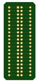
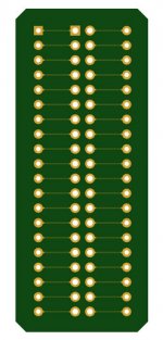
adapter-pcb-back.jpg
 
My board arrived - thanks much!

Do you happen to have a list for the other parts required? I'm not very good at part manufacturer website spelunking, I will confess.

-Kevin
 
David...

Looking at the BOM in your documentation, you have this part listed: https://www.digikey.com/product-detail/en/assmann-wsw-components/ADIP-40Z-LC/HDP40S-ND/924326

The problem is that it's backordered with a lead time of 20 weeks - sometime in December.

I'm far from an electronics expert - I know what various parts do, I have some moderate soldering skills. But making sure I have a suitable substitute identified is beyond me. Thus, I was wondering if you could let me know if this part (https://www.digikey.com/product-detail/en/cw-industries/CWR-130-40-0203/CDP40S-ND/1122542) is a suitable replacement? If not, do you know a Digi-Key part that is?

Thanks much!

-Kevin
 
Try this link to alternatives

https://www.digikey.com/products/en...01&quantity=0&ColumnSort=0&page=1&pageSize=25

Looking closely at the image of the one at top it appears it has the odd/even swap issue I found with the ones I got off ebay.
For those that have ordered the dip header and have the swapping issue, please let me know.
If you haven't as yet ordered the dip plug, I can send you an adapter boards with pins that will avoid the use of the dip plug.

adapter-pcb-back.jpg

Let me know if you have any issues and I can solve the problem for you.


David...

Looking at the BOM in your documentation, you have this part listed: https://www.digikey.com/product-detail/en/assmann-wsw-components/ADIP-40Z-LC/HDP40S-ND/924326

The problem is that it's backordered with a lead time of 20 weeks - sometime in December.

I'm far from an electronics expert - I know what various parts do, I have some moderate soldering skills. But making sure I have a suitable substitute identified is beyond me. Thus, I was wondering if you could let me know if this part (https://www.digikey.com/product-detail/en/cw-industries/CWR-130-40-0203/CDP40S-ND/1122542) is a suitable replacement? If not, do you know a Digi-Key part that is?

Thanks much!

-Kevin
 
Last edited:
Back
Top