• Please review our updated Terms and Rules here

TRS Model 1 monitor conversion.

NeXT

Veteran Member
Joined
Oct 22, 2008
Messages
8,149
Location
Kamloops, BC, Canada
By chance I stumbled upon an RCA XL-100 in a back alley which is what Tandy's monitor for the Model 1 is based off of.

100_1683.jpg

TrsMonitor-1L.jpg

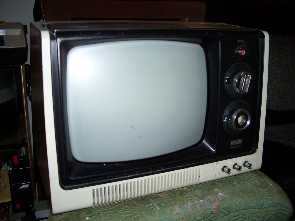
This is awesome as it means I don't ahve to use random crap to keep my current TV in tom of the expansion box from tipping over as it's designed for this TV.
Anyways, I'm trying to figure out how to connect the computer to the TV seeing as how Tandy's version lacked an RF tuner. Do I just need a composite video jack or something? I know some newer TV's accept composite video internally but I'm not sure about something this old. Wikipedia states that there is some special board inside the system that allows you to connect the computer up but I need insight on that as well as if the sync loss fix still needs to be performed.
 
By chance I stumbled upon an RCA XL-100 in a back alley which is what Tandy's monitor for the Model 1 is based off of.

This is awesome as it means I don't have to use random crap to keep my current TV in tom of the expansion box from tipping over as it's designed for this TV.
Anyways, I'm trying to figure out how to connect the computer to the TV seeing as how Tandy's version lacked an RF tuner. Do I just need a composite video jack or something? I know some newer TV's accept composite video internally but I'm not sure about something this old. Wikipedia states that there is some special board inside the system that allows you to connect the computer up but I need insight on that as well as if the sync loss fix still needs to be performed.

The Model I monitor used a video interface card that the front input cable attached to. The card was held in place by a couple of metal slot clips that the board snapped down into and then fed the rest of the video circuitry. The card was based around a 6N135 opto-isolater and some smoothing and shaping circuitry (some passive components and a few transistors).

It was a pretty simple circuit which I never committed to memory but my service manual should have a board shadow mask (single sided board) and the component layout.

Syncing and positioning was done from the keyboard itself video a couple of pots and a couple of CMOS chips.
 
That's pretty amazing that they used the same exact case... I guess if you popped off the TRS-80 logo plate, you'd see the holes where the clicker knobs would go on the TV. And I always thought the "V" above the output cable stood for "Video output"... but now I see that hole was originally used for the TV's Vertical hold adjustment!

Somewhere I recall reading in the TRS-80 literature that the monitor was a "TV set specially modified to increase the video bandwidth to the full 6 MHz necessary to crisply display 64-column text" (as opposed to a standard TV tuner, which filters out everything above 3 MHz to prevent the NTSC color subcarrier from interfering with the picture, thus causing a loss of resolution). I believe Apple used the same trick with their later IIe-series color monitor, with the color/B&W switch under the front panel; when you switch it into B&W mode, it bypasses the color filter, allowing it to display readable 80-column monochrome text.
 
Okay, so there is somethign involved in the TV that relates to the system. Would you by chance have a schematic and parts list for that board?
 
I believe the schematic for the TRS-80 monitor is in the service manual, along with the schematic for the video interface. I've modified black and white TV's for direct video input before. It's not really hard, just there are a couple of things you have to watch out for. This set, like most sets of this era, is hot chassis. Therefore, you must be sure to use an optoisolator to isolate the video signal from the computer, or use an isolation transformer to power the television. The TRS-80 monitor uses an optoisolator. This is why the funny five pin cable - the computer powers the optoisolator in the TV, from the 5v signal in the cable. Other than that, the signal is standard composite video.

The basic procedure is to disconnect the video signal from the RF stage at the base of the first video amplifier transistor (or grid of the 1st video amplifier tube, in a tube type set), and inject the signal there. Don Lancaster's TV Typewriter Cookbook gives some more information on the process.

-Ian
 
Back
Top