• Please review our updated Terms and Rules here

VGA text mode resolution/graphics experiments

mcs_5

Experienced Member
Joined
Dec 21, 2019
Messages
171
Location
Denmark
I have been experimenting with a home-made graphics (or rather text) adapter. Based on the MDA concept, with a character ROM and a shift register generating the video signal. But I'm trying to generate a VGA-compatible signal - which partly works...

What resolution does standard VGA 80x25 text mode use? My googling tells me either 640x400 or 720x400. I'm using 60x400 currently, using the timing shown here: http://tinyvga.com/vga-timing/640x400@70Hz

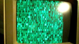
The horizontal and vertical sync frequency is correct (tested with a frequency counter), and the sync signals look correct on the scope. But the picture is not quite right. Using either an IBM 8513 or a slightly newer KFC monitor, I get approx what's shown on the photo. The image is too far left, and a bit too high. If my horizontal sync is a bit off, I guess this could move the picture left. But I don't understand the extra height. I'm sure I have the correct number of lines for the vertical sync and front/back porch. Should 640x400 work on a 8513?

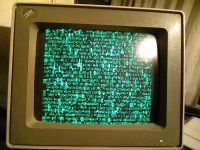
The image is actually sharp - the phone camera just wouldn't focus ;)
 

Attachments

  • photo61079.jpg
    photo61079.jpg
    190.4 KB · Views: 2
You might have an issue with sync polarity? My vague off the top of my head recollection is something along the lines that the 400 line VGA text (and double-scanned 200 line graphics) mode is the “same” in terms of frequency as the 350 line high-res EGA graphics backwards compatibility mode but there’s something about the sync signal polarity or... something, that signals the monitor to change the framing. Maybe that’s why your image is vertically stretched, it’s going to “EGA mode”?

I don’t *think* the monitor will care about the dot clock difference between 640 and 720 pixel lines.
 
Yes, I did consider the EGA possibility... I just looked it up, and your memory is correct. Sync polarity is flipped for the EGA mode.

So did I get it wrong? Does negative horizontal sync mean the sync pulse is at 0V, or that the sync line is normally at 0V? I have the sync pulse at 0V, but I can try changing the polarities...

My design is an 8-bit ISA card - not quite ready for prime time. The transistor colour mixing circuit doesn't work - it's too slow. I will probably switch to 6 AND gates instead. The CRTC is a 8051-compatible MCU, so the timing should be flexible enough to get it working :)

MDA-VGA2.png
 
So did I get it wrong? Does negative horizontal sync mean the sync pulse is at 0V, or that the sync line is normally at 0V? I have the sync pulse at 0V, but I can try changing the polarities...

When I google this myself I found this:

http://martin.hinner.info/vga/timing.html

It says in 350 line mode the Hsync is positive, Vsync negative, in 400 line mode it's reversed, (hsync -, vsync +), and 480 is negative for both. If you're already doing a negative-going hsync are you also doing the positive vsync? If that's also negative then the monitor might be in its "480" mode and, since the 8513 is a fixed-frequency screen it's giving you that strange output? (IE, it's outside of the monitor's supported resolutions, but not so off it's failing to sync entirely?)

The CRTC is a 8051-compatible MCU, so the timing should be flexible enough to get it working :)

Your project sounds a bit like a spiritual cousin of my own slowly-progressing video project; I'm targeting composite instead of VGA, but also using an MCU as a "CRTC", in my case an Atmel AVR8.

https://www.youtube.com/watch?v=J1p70xal80M
 
If you're already doing a negative-going hsync are you also doing the positive vsync?
Yes.

If that's also negative then the monitor might be in its "480" mode and, since the 8513 is a fixed-frequency screen it's giving you that strange output? (IE, it's outside of the monitor's supported resolutions, but not so off it's failing to sync entirely?)
I'm not sure what resolutions the 8513 supports - I know it does 640x480 and 1024x768 interlaced. But I guess it must support 640x400 for the 320x200 MCGA mode?

But the fact that the KFC monitor displayed the same "errors" makes me think there's some problem with my timing. The KFC monitor has phase/height controls, but the image was at the same location as the 8513 before I touched the pots. A Dell LCD monitor centred the image automatically, so it's not too far off I guess...

I'll try having a look at work, if I have time. The scope is better there ;)

Your project sounds a bit like a spiritual cousin of my own slowly-progressing video project; I'm targeting composite instead of VGA, but also using an MCU as a "CRTC", in my case an Atmel AVR8.

https://www.youtube.com/watch?v=J1p70xal80M
Yes, it does look related :)

I just use the MCU to control the timing also. I run it on the dot clock, so it should be able to generate sync signals in sync with the video.

Like your breadboards :)
I would never get something like that completed...
 
Yeah, I'm curious what's off if you have the sync polarity right. The 8513 should definitely be fine with the 400 line mode because, yeah, in addition to the text mode is supports both the 320x200 MCGA 256 color mode and all the backwards-compatible 320 and 640 pixel wide x 200 (double-scanned) EGA and CGA modes. It could just be really picky about front/back porch positioning, maybe?

I just use the MCU to control the timing also. I run it on the dot clock, so it should be able to generate sync signals in sync with the video.

I've been mulling how to make my dingus do VGA in addition to composite. The AVR I'm using is only rated to run at 20mhz so the standard 25.175 mhz would technically be out-of-spec if I ran 1:1 with the pixel clock like I do now, but I'm also heard they're pretty tolerant of overclocking so maybe it'll be Just That Easy.

(Otherwise some of the tricks I've done with GAL state machines would probably let me tinker up a way to run the MCU at an even fraction of the full pixel clock, but it'll be messier.)

Whatever you figure out here might definitely be of use to me since I'd probably also be interested in the 400 line mode; it's a better fit than the square-pixel one for the goofy stuff I want to do.

Like your breadboards :)
I would never get something like that completed...

I'm officially blaming getting really busy at work for why I've been stalled on the project for the last month or so, but I have also had a couple of pretty frustrating sessions of "loose wire" debugging that made me decide it's probably time to go ahead and spin up a PCB for the video section before moving further to the computer integration part, just for my own sanity. :p

Looking at your PCB I'm guessing you're using one of those dual-ported RAM chips for the video buffer? I'm an idiot and really wanted enough RAM to do raster graphics so, yeah, I'm stuck with those extra moving parts for buffering/cycle sharing.
 
I've been mulling how to make my dingus do VGA in addition to composite. The AVR I'm using is only rated to run at 20mhz so the standard 25.175 mhz would technically be out-of-spec if I ran 1:1 with the pixel clock like I do now, but I'm also heard they're pretty tolerant of overclocking so maybe it'll be Just That Easy.

(Otherwise some of the tricks I've done with GAL state machines would probably let me tinker up a way to run the MCU at an even fraction of the full pixel clock, but it'll be messier.)
I was thinking that I needed to run things at half speed - either because of clock limitations, or because of the number of clock cycles needed for certain instructions. Then I discovered the STC8 series, that would run at 33MHz, and do most of the instructions I needed in 1 cycle :)

Looking at your PCB I'm guessing you're using one of those dual-ported RAM chips for the video buffer? I'm an idiot and really wanted enough RAM to do raster graphics so, yeah, I'm stuck with those extra moving parts for buffering/cycle sharing.

Yes. Dual-port is easy, when you need 2000 bytes of RAM ;)

I also have raster graphics plans. But that gets more complicated, if you want to make something kinda compatible. Then I suddenly have to emulate the registers of the CRTC, and add extra status/configuration registers. As well as manage shared access to the RAM. I wanted to get something simple working first :)
 
Some progress... No time at work, so I did some more experimenting today.

filedata/fetch?filedataid=61184
wAAACH5BAEKAAAALAAAAAABAAEAAAICRAEAOw==


I tried switching the polarity of both syncs, and it looks like I've gotten the "EGA" mode now. The image is centred, and the height looks correct for 350 lines. So why didn't I get the correct position and height in the 400 line mode? The timing should be the same, with only the sync polarity difference. Still hope I get some measurement time at work (I'm only there one day a week).

The image above is just the card connected to a power supply, so the contents are just the random data in the RAM.

Installing the card in a turbo-XT motherboard got me this:

filedata/fetch?filedataid=61183
wAAACH5BAEKAAAALAAAAAABAAEAAAICRAEAOw==


The BIOS obviously has a stutter. And the board has an absurd amount of memory ;)

Not sure why the first line has some corruption...
 
Weird - I can see them here, but they're not in the "Photo Album". Guess I used "Upload Attachments" instead of "Upload"?
Here's another try :)
 

Attachments

  • photo61183.jpg
    photo61183.jpg
    250.3 KB · Views: 2
  • photo61184.jpg
    photo61184.jpg
    254.3 KB · Views: 2
Installing the card in a turbo-XT motherboard got me this:
<snip>
The BIOS obviously has a stutter. And the board has an absurd amount of memory ;)

Heh. I had to smooth out some doubled character issues with my board, related to the timing of the shift register loads. Mine were usually at the *end* of the line. ;)

You said you're only using a 2K chip, so on the PC interface are you just skipping every-other address and not dealing with attribute memory?
 
Heh. I had to smooth out some doubled character issues with my board, related to the timing of the shift register loads. Mine were usually at the *end* of the line. ;)
I guess the shift register must get loaded twice with the same byte. Haven't found the bug yet...

You said you're only using a 2K chip, so on the PC interface are you just skipping every-other address and not dealing with attribute memory?
Yes, I'm just ignoring the attribute bytes for the time being. I only enable the RAM when A0 is low.
 
I guess the shift register must get loaded twice with the same byte. Haven't found the bug yet...
Looks like I found it. Might actually be an "undocumented feature" in the MCU. The counter I'm using for the memory address gets loaded at the beginning of each line. When I send it the first pulse, it doesn't increment its value. So now I load the counter, send it two pulses after loading the shift register the first time. This seems to work finally. Makes no sense to me, that the timer should require two pulses to count from 0 to 1, but only one pulse to count from 1 to 2...
 
Fun. The AVR MCU I use doesn't have anything as smart as a counter, the address generation loop is adding the increment to a 16 bit int, shoving the value out two 8-bit ports, and padding the loop with NOPs through the active area. (IE, it's entirely cycle counting.) That's why I resorted to adding an external state machine to handle coordinating the shift register loading and buffer control that I can just tell to "go" at the start of a line and turn off at the end instead of trying to pulse the lines in software. The pitfall of the approach is fine-tuning the cadence between the address bus updates and the operations the state machine is doing; you don't want to update the address bus in the middle of a read, and if you don't turn off the shift loads in time at the end you'll get a bonus character. :)
 
Back
Top