flaviosr
Experienced Member
Dear Group,
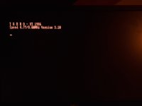
I have a NoName clone with a strange behavior.
If the PSU is not connected to the mobo and I turn it on, it starts and, for example, the HDD and the FDD turn on.
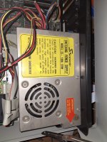
If the PSU is connected to the mobo and I turn it on, nothing happens... the PSU remains turned off.
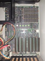
Something in the mobo or in the PSU (or both)?
Thank you
I have a NoName clone with a strange behavior.
If the PSU is not connected to the mobo and I turn it on, it starts and, for example, the HDD and the FDD turn on.
If the PSU is connected to the mobo and I turn it on, nothing happens... the PSU remains turned off.
Something in the mobo or in the PSU (or both)?
Thank you

")