Holmes
Experienced Member
My XT-IDE Setup
My XT-IDE Setup
OK. After not finding anyone who had attached their HD to the XT-IDE, I decided I didn't want to drill my beautiful XT-IDE. I still wanted a robust mount for the HD, and I was keeping both my original full-height floppy drives in my 5150. So what to do?
I am using a laptop HD (2.5 in), so it's fairly diminutive. I was looking around the open case of my IBM 5150, and noticed that since the XT-IDE is a very short card, there's lots of room in the remainder of the slot. I also noticed that on the front side of the machine, there are pairs of holes in the chassis that normally hold the plastic "guides" that the full-length cards slide into to help them stay in place. I put these thoughts together and decided to fashion my own HD mount.
I looked around Home Depot and decided on using a 8"x8" piece of galvanized steel flashing which came folded 90-degrees in the middle for $0.62. I also bought a pack of #4-40 screws and nuts for $0.98. These screws will fit through the holes in the front of the IBM chassis perfectly.
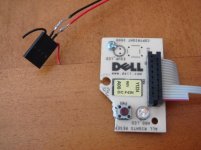
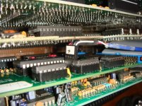
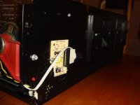
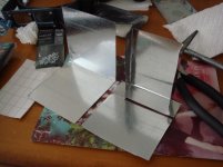
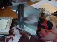
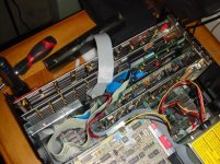
Attached are pictures of my project and the results. The flashing is pretty easy to bend with the help of pliers. Whenever you need to make a bend, hold the pliers 90-degrees to the line you want to bend on, start at one end, and work your way across gradually, bending bit at a time, and moving the pliers along by about 1 cm each time. This way, you can make nice, fairly clean bends. The flashing is also easy to cut. I used a pair of heavy duty scissors. The only thing is to be careful of the sharp edges and file them down as you make them.
I measured and marked the holes, marked the hole points with a pen first, then by nailing them with a nail and hammer to make a dent (using a piece of scrap wood underneath), and then used the dent as a guide for the drill.
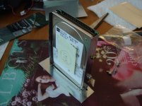
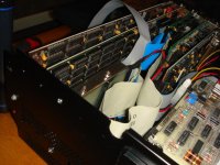
I mounted the bracket I made to the front of the PC chassis with the #4-40 screws and nuts. Then I slid the HD into the bracket and attached it with just the 2 screws on the "top" side. I found this to be plenty solid enough.
I'm thrilled about how it turned out. The mount is very solid, the HD can easily be removed by taking out the screws on top. It holds the HD in the same slot as the XT-IDE, so it doesn't take up any other space for the other cards. And it cost me under $2 and 1 afternoon. You could probably also adapt this for a full-size IDE drive just as easily.
Hope this helps someone!


