hargle
Veteran Member
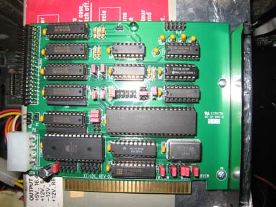
This is the main page for the XTIDE project, revision 2 cards. This card features the same basic design as the original XTIDE, using 74xxx logic parts, but adds support for a high speed UART, a larger boot ROM, and built in "chuck mod" to improve drive performance.

[h="2"] Feature list [/h]
* Works "as you'd expect" as a functioning IDE controller for 8-bit ISA slots. Just attach up to 2 PATA hard drives to a cable and start using it.
* No drivers to load. All HDD support is added through the onboard boot ROM (technically, a 'BIOS expansion ROM').
* Onboard boot ROM (EEPROM type of ROM) can be flash upgraded. No ROM programmer required.
* Supports drives of any size. There are restrictions in the operating system though (DOS 6.22 limits drive size to 8.4Gb)
* The UART (optional) allows the card to boot over a serial link from a high speed modern computer, reading and writing to an .IMG file that represents a bootable hard disk image.
* Supports most Compact Flash devices attached to CF->IDE converters.
* Supports most DOM devices. (see test results page below)
* Adds a boot menu (optional) to your machine- Boot to any drive attached to your computer, including the B: drive!
* Onboard power connector for powering either CF devices (5 volts) or standard HDDs (12 volts) for machines without spare wiring from the power supply (such as the IBM model 25).
[h="2"] High resolution photos [/h]
Photo #1 ( Note: 28C64 ROM in use - jumpers K2 and K1 are incorrectly set for that. )
Photo #2 ( Note: Optional UART circuitry not fitted. )
[h="2"] Modes of operation [/h]
There are two possible hardware 'modes' of operation. The mode that is used is selected by jumpers on the card.
Compatibility Mode
'Compatibility' means IDE hardware compatibility with an (unmodified) XT-IDE revision 1 card. If your revision 2 card is jumpered for Compatibility mode, the 'device type' option within version v2.0.0 beta 3 of the 'XTIDE Universal BIOS' needs to be set to 'XTIDE rev 1'.
Hi-Speed Mode
During production of the XT-IDE revision 1 card, some people made a modification to both the card and the BIOS software, in order to make the card run faster. That modification to revision 1 cards became known as the 'Chuck mod'. The hardware component of that modification (there is both a hardware and software component) has been incorporated into the XT-IDE revision 2 as 'Hi-Speed Mode'.
As for the software component of the modification, that is in the BIOS: If your revision 2 card is jumpered for Hi-Speed mode, the 'device type' option within version v2.0.0 beta 3 of the 'XTIDE Universal BIOS' needs to be set to 'XTIDE rev 2 or modded rev 1'.
[h="2"] BIOS [/h]
The XT Universal BIOS can be downloaded from http://code.google.com/p/xtideuniversalbios/
Versions earlier than 2.0.0 are intended for XT-IDE revision 1, not XT-IDE revision 2. If you want to try a BIOS version earlier than 2.0.0, then note that:
* your XT-IDE revision 2 card will need to be jumpered for Compatibility mode, and
* there is no UART support.
Presently (NOV13), 'v2.0.0 beta 3' is the latest version. When configuring that BIOS, the 'device type' option needs to be set according to the mode that the XT-IDE revision 2 card is jumpered for:
* XT-IDE rev 2 jumpered for Compatibility mode: Set the 'device type' option to 'XTIDE rev 1'
* XT-IDE rev 2 jumpered for Hi-Speed mode : Set the 'device type' option to 'XTIDE rev 2 or modded rev 1'
[h="2"] Schematic diagram [/h]
http://n8vem-sbc.pbworks.com/w/browse/#view=ViewFolder¶m=XT-IDE V2
[h="2"] Jumper settings [/h]
There are two options for jumper diagrams:
Option #1
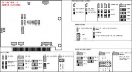
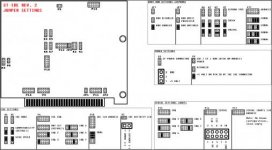
XT-IDE REV.2 jumper settings
Option #2
1. Basic IDE functionality
2. Boot ROM
3. Optional UART
Other information
Note that changing the I/O address requires a BIOS re-flash so that the BIOS knows where you moved the I/O space to.
P9 near the IDE connector is a power enable/disable jumper to pin 20 (Vcc) If you are using a DOM or other low power device that can accept 5 volts on pin 20 to power the device itself, put a jumper on P9. Then you won't need an external power cable.
[h="2"] Resistor R6 [/h]
A design error in the XT-IDE revision 1 card, which carried through to the revision 2 card, concerns the 'cable select' functionality (CS) of the IDE specification.
Discussion of this design error in the XT-IDE appears in the XT-IDE thread starting [here].
For a lot of XT-IDE users, that won't be a problem, because the IDE device in use will probably be set to 'master', not CS.
If the IDE device that you attach to the XT-IDE does not have master/slave/CS jumpers, then it is possibly using CS.
Note that a lot of IDE-to-CF adapters have master/slave jumpers.
Should you wish to correct the design error, replace R6 with a wire link (photo), or bridge the ends of R6 using a piece of wire.
[h="2"] Known problems [/h]
SYMPTOM: The XT-IDE card 'sees' the CF card, but will not boot from it.
CAUSE: Non-standard boot sector on CF card.
FIX: Use the /MBR option of FDISK.EXE (from DOS version 5 or later) against the CF card. So, after booting from a DOS 5 (or 6) boot floppy, enter: FDISK /MBR
SYMPTOM: On an IBM 5150 or 5160, the XT-IDE card 'sees' the CF card, but will not boot from it.
CAUSE: Motherboard configuration switches set for 3 or 4 floppy drives.
NOTE: Seen with XT Universal BIOS verion 'v2.0.0 beta 3'. Other versions may be affected.
NOTE: Two CF cards were used - one containing DOS 3.3 and the other containing DOS 6.22
[h="2"] Test results [/h]
http://www.vintage-computer.com/vcforum/showwiki.php?title=XTIDE+TestResults
[h="2"] Bill of Materials [/h]
[h="2"] Assembly notes [/h]
Some notes for building the card:
* SIP resistors are mounted with the printing facing down, toward the ISA connector.
* The 14 decoupling caps are not polarity sensitive.
* The 5 caps around the 232 driver IC are polarized. Note the + mark on the PCB must match the + on the cap.
* The single large cap is also polarized.
* The LED is polarized. It has one side flattened to indicate polarity. Match the flattened side of the LED with the PCB silkscreen.
* Pin 1 for the IDE connector is down, closest to the ISA connector.
* Pin 1 for the 9 pin serial header is on the left side (look for the square hole on the back of the PCB).
* The card can self-program the EEPROM, so don't worry about needing an EEPROM burner to get a complete card. In fact the card can actually function AS an EEPROM programmer; the XTIDECFG flash program available with the BIOS allows for ROMs between 8 and 64k to be written.
[h="2"] Booting via UART [/h]
Supporting software, serdrive.exe and FreeDOS.img, is here.
Click here for instructions.
Where in those instructions it specifies "SerDrive ImageFile.img", you will use "SerDrive FreeDOS.img".
Note that IMG drives show up as normal drive letters in DOS. So you have the option of booting to a local drive and then accessing the serial drive as D: or E:.

[h="2"] Feature list [/h]
* Works "as you'd expect" as a functioning IDE controller for 8-bit ISA slots. Just attach up to 2 PATA hard drives to a cable and start using it.
* No drivers to load. All HDD support is added through the onboard boot ROM (technically, a 'BIOS expansion ROM').
* Onboard boot ROM (EEPROM type of ROM) can be flash upgraded. No ROM programmer required.
* Supports drives of any size. There are restrictions in the operating system though (DOS 6.22 limits drive size to 8.4Gb)
* The UART (optional) allows the card to boot over a serial link from a high speed modern computer, reading and writing to an .IMG file that represents a bootable hard disk image.
* Supports most Compact Flash devices attached to CF->IDE converters.
* Supports most DOM devices. (see test results page below)
* Adds a boot menu (optional) to your machine- Boot to any drive attached to your computer, including the B: drive!
* Onboard power connector for powering either CF devices (5 volts) or standard HDDs (12 volts) for machines without spare wiring from the power supply (such as the IBM model 25).
[h="2"] High resolution photos [/h]
Photo #1 ( Note: 28C64 ROM in use - jumpers K2 and K1 are incorrectly set for that. )
Photo #2 ( Note: Optional UART circuitry not fitted. )
[h="2"] Modes of operation [/h]
There are two possible hardware 'modes' of operation. The mode that is used is selected by jumpers on the card.
Compatibility Mode
'Compatibility' means IDE hardware compatibility with an (unmodified) XT-IDE revision 1 card. If your revision 2 card is jumpered for Compatibility mode, the 'device type' option within version v2.0.0 beta 3 of the 'XTIDE Universal BIOS' needs to be set to 'XTIDE rev 1'.
Hi-Speed Mode
During production of the XT-IDE revision 1 card, some people made a modification to both the card and the BIOS software, in order to make the card run faster. That modification to revision 1 cards became known as the 'Chuck mod'. The hardware component of that modification (there is both a hardware and software component) has been incorporated into the XT-IDE revision 2 as 'Hi-Speed Mode'.
As for the software component of the modification, that is in the BIOS: If your revision 2 card is jumpered for Hi-Speed mode, the 'device type' option within version v2.0.0 beta 3 of the 'XTIDE Universal BIOS' needs to be set to 'XTIDE rev 2 or modded rev 1'.
[h="2"] BIOS [/h]
The XT Universal BIOS can be downloaded from http://code.google.com/p/xtideuniversalbios/
Versions earlier than 2.0.0 are intended for XT-IDE revision 1, not XT-IDE revision 2. If you want to try a BIOS version earlier than 2.0.0, then note that:
* your XT-IDE revision 2 card will need to be jumpered for Compatibility mode, and
* there is no UART support.
Presently (NOV13), 'v2.0.0 beta 3' is the latest version. When configuring that BIOS, the 'device type' option needs to be set according to the mode that the XT-IDE revision 2 card is jumpered for:
* XT-IDE rev 2 jumpered for Compatibility mode: Set the 'device type' option to 'XTIDE rev 1'
* XT-IDE rev 2 jumpered for Hi-Speed mode : Set the 'device type' option to 'XTIDE rev 2 or modded rev 1'
[h="2"] Schematic diagram [/h]
http://n8vem-sbc.pbworks.com/w/browse/#view=ViewFolder¶m=XT-IDE V2
[h="2"] Jumper settings [/h]
There are two options for jumper diagrams:
Option #1
XT-IDE REV.2 jumper settings
Option #2
1. Basic IDE functionality
2. Boot ROM
3. Optional UART
Other information
Note that changing the I/O address requires a BIOS re-flash so that the BIOS knows where you moved the I/O space to.
P9 near the IDE connector is a power enable/disable jumper to pin 20 (Vcc) If you are using a DOM or other low power device that can accept 5 volts on pin 20 to power the device itself, put a jumper on P9. Then you won't need an external power cable.
[h="2"] Resistor R6 [/h]
A design error in the XT-IDE revision 1 card, which carried through to the revision 2 card, concerns the 'cable select' functionality (CS) of the IDE specification.
Discussion of this design error in the XT-IDE appears in the XT-IDE thread starting [here].
For a lot of XT-IDE users, that won't be a problem, because the IDE device in use will probably be set to 'master', not CS.
If the IDE device that you attach to the XT-IDE does not have master/slave/CS jumpers, then it is possibly using CS.
Note that a lot of IDE-to-CF adapters have master/slave jumpers.
Should you wish to correct the design error, replace R6 with a wire link (photo), or bridge the ends of R6 using a piece of wire.
[h="2"] Known problems [/h]
SYMPTOM: The XT-IDE card 'sees' the CF card, but will not boot from it.
CAUSE: Non-standard boot sector on CF card.
FIX: Use the /MBR option of FDISK.EXE (from DOS version 5 or later) against the CF card. So, after booting from a DOS 5 (or 6) boot floppy, enter: FDISK /MBR
SYMPTOM: On an IBM 5150 or 5160, the XT-IDE card 'sees' the CF card, but will not boot from it.
CAUSE: Motherboard configuration switches set for 3 or 4 floppy drives.
NOTE: Seen with XT Universal BIOS verion 'v2.0.0 beta 3'. Other versions may be affected.
NOTE: Two CF cards were used - one containing DOS 3.3 and the other containing DOS 6.22
[h="2"] Test results [/h]
http://www.vintage-computer.com/vcforum/showwiki.php?title=XTIDE+TestResults
[h="2"] Bill of Materials [/h]
Code:
from jameco.com:
Part #           Description                  Qty   Notes
25523 	       @ CAP,MONO,.1uF,50V,20%        14 - decoupling caps
1945428        @ CAP,RADIAL,47uF,35V,         1
45129 	       IC,74HCT688                    3
46316 	       IC,74LS04                      1
46375 	       IC,74LS08                      1
46607 	       IC,74LS138                     1
47466 	       IC,74LS32                      1
64418 	       IC,SN74F573N,DIP-20,           3
287144 	       IC,74F245,DIP-20,              1
698576 	       DUAL EIA-232 DRIVERS           1
53605 	       HEADER,RT MALE,2RW,40 CONT,    1	 - right angle IDE connector
109576 	       HEADER,.1"ST MALE,1RW,3PIN,    6
117197 	       HEADER,ST MALE,2RW,80 PIN,     1	 - break apart for the 2x5's and single jumpers
41111 	       @ SOCKET,IC,40 PIN,.600",TIN,  1
112214 	       @ SOCKET,IC,14PIN,DUAL WIPE,   3
112248 	       @ SOCKET,IC,DUAL WIPE,20PIN    7
112432 	       @ SOCKET,SHORTNG BLKS,RED,CLSE 16
112272 	       @ SOCKET,IC,DUAL WIPE,28PIN    1
526205 	       @ SOCKET,IC,16 PIN,390261-4,   2
333949 	       @LED,GREEN,572NM,T-1 3/4       1
691104 	       @ RES,CF,10K OHM,1/4 WATT,5%,  6
690785 	       RES,CF,470 OHM,1/4 WATT,5%     2
857160 	       MOLDED SIP,10PIN,BUSSED,10K,   3
2094389        SCREW,PAN HEAD,PPN4-40X1/4     2

Optional UART components: (You'll save a bit of money not buying these if you don't plan on using UART)

33664 	       CAP,TANT,1uF,35V,10%           5	- for the 232 driver for uart
288809 	       IC,UART,TL16C550CN,5V,DIP-40   1
133006 	       SOCKET,OSC.CRYSTAL,14POS,4-PIN 1	- special oscillator socket
117568 	       CONNECTOR,DISK DRIVE,MALE PCB  1	- molex power plug
325358 	       OSCILLATOR,7.3728MHZ,FULL CAN, 1	- high speed clock


+ from mouser.com:
556-AT28C64B   Atmel EEPROM                   1
534-9202       Keystone bracket, ISA          1

+ from Andrew Lynch:
XTIDE rev2 PCB                                1
[h="2"] Assembly notes [/h]
Some notes for building the card:
* SIP resistors are mounted with the printing facing down, toward the ISA connector.
* The 14 decoupling caps are not polarity sensitive.
* The 5 caps around the 232 driver IC are polarized. Note the + mark on the PCB must match the + on the cap.
* The single large cap is also polarized.
* The LED is polarized. It has one side flattened to indicate polarity. Match the flattened side of the LED with the PCB silkscreen.
* Pin 1 for the IDE connector is down, closest to the ISA connector.
* Pin 1 for the 9 pin serial header is on the left side (look for the square hole on the back of the PCB).
* The card can self-program the EEPROM, so don't worry about needing an EEPROM burner to get a complete card. In fact the card can actually function AS an EEPROM programmer; the XTIDECFG flash program available with the BIOS allows for ROMs between 8 and 64k to be written.
[h="2"] Booting via UART [/h]
Supporting software, serdrive.exe and FreeDOS.img, is here.
Click here for instructions.
Where in those instructions it specifies "SerDrive ImageFile.img", you will use "SerDrive FreeDOS.img".
Note that IMG drives show up as normal drive letters in DOS. So you have the option of booting to a local drive and then accessing the serial drive as D: or E:.


