• Please review our updated Terms and Rules here

Z80 interrupter. Will this circuit cut it?

per

Veteran Member
Joined
Jan 21, 2008
Messages
3,052
Location
Western Norway
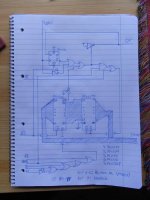
I'm fed up with one of my Z80 computer not having a VSync interrupt, or no indication on what goes on in the graphics hardware at all. Because of this, I decided to design a VSync interrupt expansion for it.

This device is pretty simple. It's designed for Interrupt Mode 2. You write the interrupt vector number with bit 7 set to an I/O port, and the device will then hopefully properly interrupt the Z80 CPU. Clearing bit 7 should disable the interrupting from the device. Interrupt is triggered if the /INT line is high when VSync triggers. /INT is pulled high by a pull-up resistor on the motherboard, and typically only the CTC will bother with interrupting.

Now, I cannot find to much discussion on the timing and hardware protocols around the Z80 interrupts. From what I understand the circuit I've come up with should work, but I'm not 100% certain. I don't really want to start ordering PCB's before I am safe this should be OK.


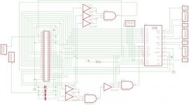
The main thing I am thinking about is when VSync is over before the interrupt is acknowledged. I problably have to use the other flip-flop in the LS74 to sample the VSync to /M1, as aborting the interupt during the acknowledge would be a bad idea.
 

Attachments

  • RIMG1028 - Copy.jpg
    RIMG1028 - Copy.jpg
    54.6 KB · Views: 1
Your circuit looks OK to me... But perhaps you could just use Z80 CTC as an interrupt controller? It is designed to work with IM2 (so no gambling there), and also will save you a bunch of logic (replaces 5 ICs with 1). You still will need an IO decode circuit, but something like 74LS138 should do.
 
Sergey's reading my mind...

If you already have a CTC installed, then just set another channel of the CTC to triggered timer mode, set the timer to its fastest mode (no prescaler), and the count to 1 with interrupt (decrement to 0) enabled. No decoders needed at all, just run VSYNC to the trigger input of the appropriate CTC channel--the polarity is programmable.

You'll get your interrupt delayed by 1 count, but if the clock is fast enough, that won't matter, as the Z80 will take longer to respond to the interrupt than the single count.
 
Thanks! using such a featured chip for a tiny task it didn't even strike my mind. I've always liked to design cirquits from scratch, but CTC is not only less chips, but more convenient as well. By using the CTC, I can use it directly with the hardware trigger, yeah, and I can in fact run it with a divided version of the dot-clock itself for very good accuracy.

The trigger channels of the motherboard CTC are all used by other things, so the best way will be to add another one on an expansion.

Now, the other big problem is: Should I bypass the priority daisy-chain from the motherboard, or use it? By using it all the chips on the MB gets higher priority than the VSync interrupt.
 
Last edited:
50 times per second though, but the problem is that there is 32K of video RAM, and every single byte access to it comes with anything between 2 to 5 additional waitstates. The hardware is fixed to use all of VRAM as a single bitplane in all of the graphics modes, so getting fast video is in itself a bit of a problem. The graphics update simply needs every microsecond it can get.

The main problem till now has been that the CPU/support chips and the graphics chipset runs from different crystalls. The motherboard CTC (highest priority in the chain) does have a countdown combination that matches the screen framerate perfectly, but due to different clocks there is a tiny bit of drift. Sampling VSync or the dot-clock will solve that problem, and allow me to time the screen updates perfectly.

I can just as well tell all the CPU support chips on the motherboard to shut up if I need the precission. That's problably the best option.
 
Last edited:
I'm not sure about some of the signals you have, but here are some comments that probably apply. I realize your plan is to add a second CTC, but you might want to puzzle these out.

Yea, the schematics pictured was the old idea. I updated it a bit as well since the one seen here, but after the CTC alternative was mentioned it is clear that's the way to go instead. This is the new idea.

All the outputs and triggers goes to pin headers since it's easy to configure/reconfigure it then. The VSync and graphics clocks are on the graphics expansion port anyways, and it's much easier to just bridge those few pins in question rather than the entire graphics-expansion header.

Pinout of the 50-pin CPU expansion port:
Code:
	Pin Number	Name	Type	Description

	1, 39, 48	GND		Ground
	2, 40, 47	+5V		+5 Volts
	3		/NMI	O**	Non-maskable interrupt
	4		/INT	O**	Interrupt
	5		/MRQ	I*	Memory Request
	6		/RES	I	Reset
	7		/IORQ	I*	Input/Output Request
	8		/M1	I*	M1 Cycle
	9		/RD	I*	Read Request
	10		/WR	I*	Write Request
	11		/EXIN	O	Data Bus Direction (same deal as with that pin in slot 8 of the IBM PC/XT)
	12		/BUSAK	I	Bus-Mastering Acknowledge
	13		/BUSRQ	O	Bus-Mastering Request
	14		Ø	I	CPU Clock (4MHz)
	15-22		D0-D7	IO	Data Bus
	23-38		A0-A15	I*	Address Bus
	41		IEOXI	I	Interrupt Priority-Chain Input
	42		IEOXO	O	Interrupt Priority-Chain Output
	43		/VIWT	I	Wait for Video 	
	44		/RFSH	I*	DRAM Refresh
	45		2CL	I	Support Clock (2MHz)
	46		/MDIS	O	Motherboard Memory Disable
	49		-12V		-12V
	50		+12V		+12V

	* These become Outputs when expansion card is Bus-Mastering.
	** These become Inputs when expansion card is Bus-Mastering.

(bigger image of schematics: https://www.dropbox.com/s/0i4ntdorzjnc0wb/aaa.png?dl=0 )
 

Attachments

  • aaa.jpg
    aaa.jpg
    21.2 KB · Views: 1
Last edited:
Back
Top