Coder
Experienced Member
- Joined
- Apr 16, 2023
- Messages
- 84
I guess I lied. The LED that indicates it's receiving power from the A/C adapter lights, but nothing else. I suspect there's a common flaw with these systems as I haven't seen any for sale that say they power on. Nor have I seen anyone with a photo or video of one booting. The only one of these I've ever seen functional was on an episode of the Computer Chronicals because it was brand new. If you want to skip to the problem and what I've tried, scroll down to the heading "The Problem". I want to describe the computer and it's components first. 1) Because it's a neat system and I want to show it off and 2) because knowing how things go together may help diagnose the problem.
The System (Photos are of my parts machine. The "good" one is all taken apart right now)
It's an interesting little machine. It's form factor is... different. It's a clamshell design, with the screen folding down over the keyboard. But when opened, the keyboard can be detached, allowing the user some flexibility. It has a battery pack that takes up half of the available space in the lower case, so Zenith had to get creative with packaging it's innards. Taking it apart is like solving one of those expensive puzzle boxes made to look like ordinary things. You have to twist and turn and contort the pieces to get them to come out.
Zenith sold mainly to government institutions and not to the public, so unfortunately information is sparse. Since they didn't sell to directly to the public, people didn't grow up playing games or working on homework on them. So the nostalgia factor is low. But there's something about them that I'm drawn to. Maybe it's the "just a little off" proportions, or the way the keyboard detaches. I'm not sure. But I feel the need to get one working and share it with others.

Because the battery takes up so much space, Zenith opted to locate the mainboard behind LCD panel, making for a pretty thick screen. Zenith was quite proud of that panel, by the way. It made it into virtually all of their advertising.

The mainboard is has a large large ribbon cable that runs down into the base to a daughter board that I'll call the "IO board" since it houses the hard drive, 3.5" floppy drive, and built-in modem.

In the photo above, you can see the copper colored ribbon cable coming from the mainboard and down to the IO board. On the back edge of the IO board, facing us, are two smaller copper colored ribbons. These are for the 3.5" floppy and IDE HDD data signals. There are headers on the front edge of the card for the power cables. Facing down along the back edge, you can see the array of IO ports. The large void above the IO board is where the battery usually sits. You can see the long battery power cable going up and to the left. The plastic housing for the battery is sitting to the left of the picture and doubles as the bottom base of the computer. Below the IO board is the two power boards. The two ribbon cables dangling down from the IO board connect to each of these power boards. I'm not sure why there's two different cables, but I suspect the smaller one also contains data signals. More on that later.

Power delivery on the TurboSport is odd. There is an external power brick that has two outputs listed, both with dual voltages:
27VDC, 1.8A; 37VDC, 0.18A
OR
27VDC, 0.1A; 37VDC, 1.5A
It's my belief that the first set of outputs is when the computer is running off of external power. 27VDC with a higher amperage to run the computer, and 37VDC at low amperage to slowly charge the battery. The second set of outputs, then, are for "fast charging" mode, when the computer is connected to external power, but is off. 27VDC at barely any amperage, probably just enough to control the charging logic, and 37VDC at higher amperage to quickly charge the battery. To support this theory, there's two LEDs on the case. One for "External Power" and the other for "Fast Charging".
The first, smaller power board (green, to the left) takes this 27VDC and 37VDC and does... some things... I'm not really sure. The board is labeled "PWR/LOGIC". I think it's responsible for determining whether the computer should run off external power or battery power as well as handling the logic for charging the battery. It has connections to the battery and to the other power board, so that fits my theory. But then there that ribbon cable. It has 14 pins. I think that there might be some sort of "Power OK" signal that comes back on one of these pins, but that's just a theory right now.
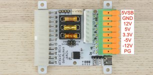
The larger power boards receives 24VDC from the smaller board. At least it's supposed to. Neither of my units ever give 12VDC to this board. That's part of the reason I think the smaller board is supposed to get some sort of signal from the ribbon saying things are OK before it does. I think the purpose of the larger board is to take the 24VDC and split it out to all of the lower voltages the computer needs to operate. Likely +12VDC +5VDC and possibly -12VDC and or -5VDC. I've yet to find a technical manual for this computer, so I don't know what voltages it expects. There are a LOT of pins coming from the output of this board, but if I remember correctly, I found that many of them are connected to each other in batches. So the number of pins is likely just a way of allowing the small, flexible ribbon cable to handle the amps the computer needed to pull. By dividing the load over many smaller wires instead of a few larger ones, they could keep the cable very flexible and less prone to damage from moving. Again, that's my theory.
Which brings us to...
The Problem
Absolutely nothing happens when I hit the power button. No indication of life whatsoever. I've tested the power adapter and it's giving me the expected voltages. I haven't checked at what amperages. I honestly don't know how to check that, or if I can with my meter. Maybe it's time to figure out how my amp clamp works... But I suspect that it won't draw significant amperage until it actually tries to turn on.
I checked for voltage where the first power board connects to the second and there is never voltage there. I've supplied 24VDC to the battery connection and had the same results. My bench power supply never indicated significant power draw when I did this, except when the power button is held in. But still no signs of life.
I tried disconnecting as many components as I could. The modem is on it's own daughterboard, so I removed that. I disconnected the drives. But still nothing.
It has one of those Dallas SmartBattery CMOS/Battery combos and I've heard of instances of computers not booting if the battery was dead, so I drilled through the plastic of the Dallas SmartBattery, severing it's connection to it's internal battery, and attached a CR2032. But that didn't seem to bear fruit either. At this point, I'm at a loss. I'm unsure of where to go next. If anyone has ideas of things to try or thoughts on why it may not boot, I'd love to hear them. I'd really like to save it.
The System (Photos are of my parts machine. The "good" one is all taken apart right now)
It's an interesting little machine. It's form factor is... different. It's a clamshell design, with the screen folding down over the keyboard. But when opened, the keyboard can be detached, allowing the user some flexibility. It has a battery pack that takes up half of the available space in the lower case, so Zenith had to get creative with packaging it's innards. Taking it apart is like solving one of those expensive puzzle boxes made to look like ordinary things. You have to twist and turn and contort the pieces to get them to come out.
Zenith sold mainly to government institutions and not to the public, so unfortunately information is sparse. Since they didn't sell to directly to the public, people didn't grow up playing games or working on homework on them. So the nostalgia factor is low. But there's something about them that I'm drawn to. Maybe it's the "just a little off" proportions, or the way the keyboard detaches. I'm not sure. But I feel the need to get one working and share it with others.
Because the battery takes up so much space, Zenith opted to locate the mainboard behind LCD panel, making for a pretty thick screen. Zenith was quite proud of that panel, by the way. It made it into virtually all of their advertising.
The mainboard is has a large large ribbon cable that runs down into the base to a daughter board that I'll call the "IO board" since it houses the hard drive, 3.5" floppy drive, and built-in modem.
In the photo above, you can see the copper colored ribbon cable coming from the mainboard and down to the IO board. On the back edge of the IO board, facing us, are two smaller copper colored ribbons. These are for the 3.5" floppy and IDE HDD data signals. There are headers on the front edge of the card for the power cables. Facing down along the back edge, you can see the array of IO ports. The large void above the IO board is where the battery usually sits. You can see the long battery power cable going up and to the left. The plastic housing for the battery is sitting to the left of the picture and doubles as the bottom base of the computer. Below the IO board is the two power boards. The two ribbon cables dangling down from the IO board connect to each of these power boards. I'm not sure why there's two different cables, but I suspect the smaller one also contains data signals. More on that later.
Power delivery on the TurboSport is odd. There is an external power brick that has two outputs listed, both with dual voltages:
27VDC, 1.8A; 37VDC, 0.18A
OR
27VDC, 0.1A; 37VDC, 1.5A
It's my belief that the first set of outputs is when the computer is running off of external power. 27VDC with a higher amperage to run the computer, and 37VDC at low amperage to slowly charge the battery. The second set of outputs, then, are for "fast charging" mode, when the computer is connected to external power, but is off. 27VDC at barely any amperage, probably just enough to control the charging logic, and 37VDC at higher amperage to quickly charge the battery. To support this theory, there's two LEDs on the case. One for "External Power" and the other for "Fast Charging".
The first, smaller power board (green, to the left) takes this 27VDC and 37VDC and does... some things... I'm not really sure. The board is labeled "PWR/LOGIC". I think it's responsible for determining whether the computer should run off external power or battery power as well as handling the logic for charging the battery. It has connections to the battery and to the other power board, so that fits my theory. But then there that ribbon cable. It has 14 pins. I think that there might be some sort of "Power OK" signal that comes back on one of these pins, but that's just a theory right now.
The larger power boards receives 24VDC from the smaller board. At least it's supposed to. Neither of my units ever give 12VDC to this board. That's part of the reason I think the smaller board is supposed to get some sort of signal from the ribbon saying things are OK before it does. I think the purpose of the larger board is to take the 24VDC and split it out to all of the lower voltages the computer needs to operate. Likely +12VDC +5VDC and possibly -12VDC and or -5VDC. I've yet to find a technical manual for this computer, so I don't know what voltages it expects. There are a LOT of pins coming from the output of this board, but if I remember correctly, I found that many of them are connected to each other in batches. So the number of pins is likely just a way of allowing the small, flexible ribbon cable to handle the amps the computer needed to pull. By dividing the load over many smaller wires instead of a few larger ones, they could keep the cable very flexible and less prone to damage from moving. Again, that's my theory.
Which brings us to...
The Problem
Absolutely nothing happens when I hit the power button. No indication of life whatsoever. I've tested the power adapter and it's giving me the expected voltages. I haven't checked at what amperages. I honestly don't know how to check that, or if I can with my meter. Maybe it's time to figure out how my amp clamp works... But I suspect that it won't draw significant amperage until it actually tries to turn on.
I checked for voltage where the first power board connects to the second and there is never voltage there. I've supplied 24VDC to the battery connection and had the same results. My bench power supply never indicated significant power draw when I did this, except when the power button is held in. But still no signs of life.
I tried disconnecting as many components as I could. The modem is on it's own daughterboard, so I removed that. I disconnected the drives. But still nothing.
It has one of those Dallas SmartBattery CMOS/Battery combos and I've heard of instances of computers not booting if the battery was dead, so I drilled through the plastic of the Dallas SmartBattery, severing it's connection to it's internal battery, and attached a CR2032. But that didn't seem to bear fruit either. At this point, I'm at a loss. I'm unsure of where to go next. If anyone has ideas of things to try or thoughts on why it may not boot, I'd love to hear them. I'd really like to save it.