• Please review our updated Terms and Rules here

ZX81 CPLD design

rodney

Veteran Member
Joined
Jul 14, 2022
Messages
526
In the 1990s years I have designed a few small ZX81 and ZX97 based computers. In those days I had some collaboration with Wilf Rigter who made his own version of a ZX81 with some enhancements. I used some of his ideas in my ZX81 Issue 4 project at the time.

Since then I have done some larger projects and got into using CPLDs to be able to integrate a lot of logic and help scale down PCB design sizes. Also a CPLD has many advantages such as doing a lot of development on the circuits without actually needing to rewire a lot of things on the prototype.

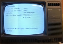
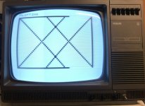
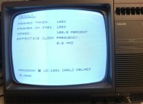
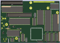
Last weekend I did a small experiment to wire a ATF1508AS onto my ZX81 Issue 4 PCB, and removing most ICs from the board, except the clock generator gate IC, CPU, RAM and ROM. After some revising and testing I found a reasonable equivalent CPLD design of the ZX81 ULA. Not 100% since the Sinclair ULA didn't need the /RFSH signal, for example, but that was also not my goal, I just wanted to realize a ZX81 in the CPLD and be left with as many spare CPLD pins as possible after completing the design. If we want, we also can figure out how not to need the /RFSH line to predict the refresh cycles, but that will only give us a single pin of the CPLD, which is not that important right now.

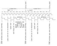
Having only the Dn lines on the CPLD pins needed some timing adjustments to be able to clock the character data before NOP is applied to the CPU, and then I needed to latch the D6 and D7 lines so they would be available for the "NOP" and "INVERT" decoding logic further along in the CPU cycle.

After finishing this first experiment, it looks attractive enough to make a computer with this idea, and I decided I will be making a PCB for this project which will include some other features in order to make the project more interesting. It's really not much work and I am doing this as a side project next to my larger designs. I am also looking into possibly running CP/M on the resulting computer, The challenge would be to merge CP/M bank switching with the ZX81 core computer, and somehow displaying the CP/M console. I am not sure if CP/M will be included but I am working on the schematic to test this idea if it would be feasible. I also want to look around which type of other interesting expansions I could include in this computer. The PCB is intended to fit inside the original ZX81 case. Later, I also will look into replacing the keyboard with something better. Maybe a RP2040 would be nice to include if some useful features could be found to make use of it.

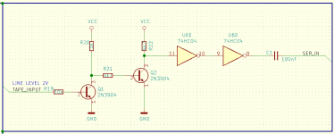
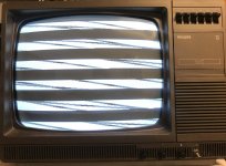
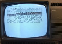
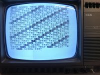
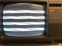
For the purpose of sharing these ideas for this very small experiment, I created a GitHub repository where you also can find my CPLD design which is able to functionally replace the ZX81 ULA. It's not fully done yet, but it is able to produce the display correctly and the keyboard is also functional. The only thing I plan to add to the ULA part of the design is to get some kind of back porch on the video output, I thought about tri stating the video output during the back porch period, and using some external circuit to take the composite signal to the back porch level during tri-state. Something like that.

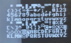
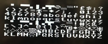
These days I am also reading Wilf Rigter's articles(I needed to search around for my old copies) and came across the CHR$128 modification which would allow for custom character sets to be realized for example for supporting games.
Does anyone know of some software which could test this modification out?

My first goal is integration, making the computer more useful, and also I want to be able to support as many games and programs as possible, so it would be useful to know which type of video enhancement related circuits would be good to include in the project in order to be able to run a larger number of games.

The ZX81-CPLD-V1 project can be found here.

I would appreciate any ideas and suggestions of expansions which could make this computer more functional.
I have some ideas and it depends on how useful, if it fits my project and how many components are needed.
If I can get CP/M to combine with the ZX81 functions, possibly a PPIDE harddisk would be nice and maybe a floppy drive.
And possibly a ZX81 program loader and saver could be realized using CP/M as the disk operating system.
CP/M is also able to read DOS diskettes which would be cool.
I know there are other solutions however having an elaborate OS would be valuable in this case in my opinion. CP/M would feel more retro.
Using bank switching, I imagine being able to switch back and forth between ZX81 mode and CP/M, and being able to run programs and data into the ZX81 computer.
I am looking at how many CPLD pins this would take with a minimal number of external components so I can get optimal use of the PCB space available in the tiny case.
It's really an advantage to be able to do all the decoding in the CPLD and this scales down the PCB area a lot.

Kind regards,

Rodney
 

Attachments

  • Img_5525s.jpg
    Img_5525s.jpg
    307.1 KB · Views: 33
Great project ! The ZX81 mostly produced video in software, and it's cool to see where this is heading.

You could probably even do what you need in a few SPLDs even - the zx81 wasn't too complex.
There is a constant need in the Sinclair community to obtain ULAs for old machines - There are some, but more is always better.
Hi cj7hawk,

Thanks for your message, I'm glad you like this project.

Definitely using a few GALs it's also possible to create a functional ZX81, I remember coming across such a project before.

For me, this little project has been initially purely experimental to see the result of using a CPLD, and for the other part I realized the potential for integration of more things thanks to having the spare pins available on the CPLD.

Certainly, I could also release a ULA replacement of the ZX81 portion of this project, which is already functional right now.
Like on a small and cheap plug-in PCB, which also could include a few components for the improved composite video output, for example.
And the ULA circuits would support 56KB of RAM by default so a builder could insert a larger RAM into the RAM footprint and easily wire a few address lines to the inserted RAM chip.

I am looking into expanding the basic circuits into CHR$128 compatibility for supporting UDG and/or lower case characters.
After I have everything included that I intend to, I will look at which things of the expanded features may possibly also be done using some connectors or a small hand wiring inside a ZX81 on an original PCB if this could enable some extra features.

Right now, CHR$128 and CP/M are the big items on my list of possible features on a replacement PCB.

While testing this, I am also looking at improving the timing of the ZX81 video control relative to the Z80 cycle inside the CPLD.
I will be drawing out some timing diagrams to get a full and exact scope of this so I can make sure to match it as precisely as possible in the CPLD logic and hopefully adapting this to additionally being able to support CHR$128 while being on the Dn lines with the CPLD.
So that this may be possible in a ULA replacement connection method.
I am looking at creating some internal signals which follow the Z80 operation closely so we can base some timing control off this.
This appears to be a possible solution to get the CHR$128 working.

If needed, I will move on for the sake of CHR$128 support to the replacement PCB design phase, and I may use the Dn' lines if this would yield better results in that regard.
Being on the Dn' data bus does have some advantages such as being able to access the RAM and ROM data during the video display phases of the CPU operation.
In this situation, I may run the forced NOPs via a transceiver which will only need the /NOP signal on a pin of the CPLD. Using a single pin to gain better access to video data is also not a big sacrifice on the CPLD.
If absolutely necessary, I will consider this route, but I am still looking into this.
After all the experimentation is finished, I will look into what portions can be added into a ULA type programming and plug in PCB.

On a side note, I have created and tested the "internal" /RFSH signal in the CPLD, and eliminated the need to use the /RFSH pin from the CPU.

Right now I am still trying to find some definitive software test of CHR$128 because it does look cool to have more characters and having the option to define your own for game tiles.
It seems like the cool ZX81 game "Alien Attack" may be able to test this out, as I am already seeing at least partial CHR$128 happening on the monitor.

I also found a character data loader file which you can break out of and it will display all the characters including the lower case letters.
This file appears to be employing the CHR$128 principle.

Next I will look at being able to alternate between ZX81 mode and CP/M mode, for example defaulting into ZX81 mode and being able to enter into CP/M mode using a switch.
It would be very cool if when entering CP/M, this would pose no restrictions during CP/M operation, that is what I will be looking into.

Anyway, I will share all the results of my experiments and make some simple small PCBs for using these inside an actual ZX81 case.
Another idea I am having is to look into featuring a single PCB which is half keyboard and the other half is a ZX81 computer.
Kind of like the ZX80 layout. This would enable proper PC keyboard key switches to be used in a little single board computer which includes many things onboard.

Maybe a full ZX97 type computer, adding more of Wilfs ideas.

I also plan to feature a separate section on my website dedicated to Wilfs super useful and interesting ZX97, EZ80 and other articles such as fast PC-ZX transfer via LPT.
What he did in his ZX97 is for a larger part not so commonly replicated so maybe I can change this also.
I remember he even had a Z80 assembler program of some kind in his ZX97, and some form of ROM DOS, able to load programs from a ROM.
He once sent me some ZX97 ROM file, I would some day like to be able to test out all of the features he included inside that file.

Kind regards,

Rodney
 
Hmm. If you're looking for future expansion possibilities, how about a ZX82 upgrade mode? You could still leave the ROM/RAM alone so a "ZX Spectrum" Loader and Basic Expansion program could sit there, Shadow the original ROM to hook the basic error handler, and then put some video mapping at $4000 -

Then you could theoretically load many Spectrum titles, since most don't reference the ROM at all, and you could even ignore the timing issues.

IIRC, the keyboard mapping is the same?

A ZX81 that is forward compatible :) That would have been an incredible upgrade during the 80s and lots of ZX80 owners would have bought it. You can even still keep it monochrome with shades of grey and then no need for a PAL encoding chip. Like they were thinking for the Pandora.

And expand a small daughterboard with the RAM preinstalled to fit into the ULA socket or z80 socket. In fact, I wonder if it's possible to install the entire thing into the z80 socket and still use the existing video encoder?

And CP/M capability would be cool - :) If you can offset the original RAM as video memory, then you can use the onboard RAM for video ram, off-board ram for TPA and have the ULA/CPU combo generate the video signals directly, treating the entire zx80 PCB as an "I/O" module.
 
Then you could theoretically load many Spectrum titles, since most don't reference the ROM at all, and you could even ignore the timing issues.
Hi cj7hawk,

I also have had such thoughts like wondering about how much compatibility to the spectrum operation would be possible with a minimal change in the logic.
Definitely I am open to look into this at some time.
I haven't looked at the Spectrum so much yet, but your suggestion makes me want to do that at some time, even if only for doing a comparison.

I will develop some stuff in terms of what's directly ahead, and maybe we can revisit this idea at some time, I will keep this in mind.

As for CP/M, I will look at basically featuring the same idea and function as ROMWBW/RC2014 in order to maintain compatibility to this brilliant solution, and try to find some bank scheme which will allow data loaded during CP/M mode to be present in memory when switching back into ZX81 mode. Something along those lines.
I will try to come up with a solution which I feel will be the most universal in nature.

What would be really cool as a later development, would be to feature CP/M output on the ZX81 video, a CP/M driver would have to be created for this purpose.
I am not nearly well versed in assembly programming (yet).
However this feature would definitively be worth someone investing some time into this.

What also would be cool would be a ZX81 basic that operates more like typical basic versions like typing in the whole keywords, and being able to move by cursor keys over the previously typed text. That would feel more professional if that would be possible.

Kind regards,

Rodney
 
If you turn the zx81 main PCB into a "Video Card and Keyboard Interface" then you could also possibly "UpClock" the video memory, use the existing RAM and ROM (with character generator ) and speed it up by a little over 2x, and have it generate 80 column video?
 
If you turn the zx81 main PCB into a "Video Card and Keyboard Interface" then you could also possibly "UpClock" the video memory, use the existing RAM and ROM (with character generator ) and speed it up by a little over 2x, and have it generate 80 column video?
Thanks for your message and for your suggestions cj7hawk,

I have had similar sentiments as you, and I also like a structured system similar to a PC.
I always feel that the Z80 missed its chance to power a professional PC system.
CP/M is the closest thing, and currently a lot is still developed for it which makes it more interesting.

I will think of what further enhancements could be done. I have had some ideas to look into changing the clock speed and possibly raising the video display system into the VGA display range. When I have time later, I may do some experiments in this regard. Right now my test setup is only hand wired and very fragile. I must soon mold this into a PCB so I have a stable test setup. So I am working right now to collect enough parts to include on a first test version PCB. I will share everything on GitHub so others also could build it if they are so inclined. Adding a CPLD into the mix really creates a pathway for enhancements.

The ZX81 display system is complicated because it combines a lot of things to make more use of what a Z80 CPU chip can do beyond the original intention of the manufacturer. Thus they turned the Z80 into a simple CRT controller. So in the future we could look into getting more efficiency from the processor. I do have some Z80s here which can run at 8MHz at least.

I created a CP/M Z80 mainboard design before, and the ROMWBW based RC2014 is a really developed concept which can really benefit any Z80 system. And I greatly admire the brilliant work of Gary Kildall, so right now I am looking into merging a CP/M capable system with the ZX81. If this is successful I will start with a "minimal version" which will fit inside an original ZX81 case. A CP/M enhanced ZX81 feels like a big step forward to start with.

Further steps may be using a RP2040 to support other enhancements for improved use of the ZX81 computer and possibly interfacing in a more modern way.

For now, I am working on finalizing the CPLD ZX81 core concept, and it's looking great, more info will follow shortly about this, I am finishing some circuit experimentation on breadboard.

Kind regards,

Rodney
 
Interesting project. I’m interested in the schematic and cpld design file so I can follow along.
Bill
Hi Bill,

Thanks for your reply and for your interest in the project.

I will continue to share all my work openly and I will update a schematic here where you can see my concept.
Most of the connectivity of the CPLD will be self evident because of the signal names.

It's a work in progress, indeed my reason for sharing the concepts openly is simply for people who are interested to be able to look at the designs.

Already I made some new progress which I will share shortly.
I will post about it here also,

Kind regards,

Rodney
 
Since you are using CPLD which greatly simplify and speed up decoding, my experience is CMOS Z80 (including relabeled Z80 from eBay) can reliably overclocked to 25.175mhz with help of CPLD. I think VGA display is quite possible.
Bill
 
Since you are using CPLD which greatly simplify and speed up decoding, my experience is CMOS Z80 (including relabeled Z80 from eBay) can reliably overclocked to 25.175mhz with help of CPLD. I think VGA display is quite possible.
Bill
Hi Bill,

Thanks for your post.
I see what you mean. I will try to obtain some faster Z80 chips.
Previously I bought some which were "rated" 20Mhz but only one of those was able to run at 8Mhz.
Though maybe it can go faster if the rest of the computer is also optimal.
Anyway, I will look for other Z80s.

I'm a fan of overclocking of any kind so I will definitely look into this.
I will try to keep all the components at faster access time ratings to have more chance of getting this to work later on.

Kind regards,

Rodney
 
I have some news about my experiments involving the CHR$128 modification.

I was having some issues with timing, so I reworked the whole logic according to the new shift register cycle timing signals controlling the ZX81 registers, and after changing to a different internal signal to generate INVERT, I was able to achieve full support for CHR$128.

So that is great news in terms of how many games with cooler graphics will be supported on the resulting ZX81.
I tested with the "Alien Attack" game, and this is now showing the whole character set correctly in CHR$128 mode.

CHR$128 is initiated by putting new character set data in RAM, and letting the Z80 REFRESH cycle control A8 during refresh.
A8 is then used to generate the character address for address bit A9' (which needs to be separated by a 1k resistor just like the other bits in a ZX81) where the UDG characters are loaded from in memory. The A9' side is connected to both RAM and ROM.

For getting CHR$128 support on a ZX81 PCB, the A0' to A9' lines need to be connected to both the RAM and ROM chips.
The A0' to A9' address lines are separated from the CPU so they can be generated by other logic during REFRESH where the character address in memory is composed.
Right at the start of the new M1/T1 cycle, the video shift register loads the character data from memory using the address generated during refresh. So there is a very short LOAD pulse to the video shift register right at the start of the CPU executed video generation cycle, after which the video bits are shifted out at 6.5MHz. The video is constantly being shifted out by subsequent video generation cycles of the CPU.

I made a diagram using Wilf Rigters explanation of the ZX81 video display generation, see the attachment.
In the diagram you can see exactly what happens where in the cycles, and that the character generation is continually running during active display periods.
I used this information to change the logic somewhat regarding the timing.
This is also necessary because I am connecting the CPLD using the ULA connections, specifically the Dn lines are used on the CPLD for I/O and decoding.
On an original ZX97 type of connection method, this would be less of an issue I expect.
Anyway, I would like my CPLD designs to also be able to be used on original ZX81 PCBs if possible.
Fortunately I have found a way to make this work in reasonable time.

Next thing requiring some attention was the tape loading input.
I want to be able to use line level audio (around 2V amplitude) to load programs from a phone or PC headphone output.
These outputs can't reach 5V or even near it so I decided to experiment with a few transistos and fed the output of the circuit through two stages of the 74HC04 which is there on the PCB anyway. Feeding their output into the CPLD input through a capacitor of 100nF resulted in really reliable tape loading with minimal need to tune the audio levels so precisely. The amplitude of the CMOS 74HC04 output is really looking good showing 5V peek to peek pulses. Previously I also worked on tape inputs without having a scope, so this time I spent a little more attention to the levels etc. I am sure the circuits can be done in many other ways anyway I am going with this method because it is working well for me without any issues. The circuit between the tape input and the CPLD also can protect it from getting damaged by over driving from an external input of "unclear" levels, be it AC or DC. Using line levels is more safe and convenient in a modern use in my opinion. Usually we will generate some tape input using a modern PC or phone.

In attachment also the CHR$128 compatible version of the ZX81 CPLD, using all the new signals for the video / character timing.
I will also upload the new quartus project to my GitHub.

Next I will have a look at CP/M support to see if it would be possible to integrate this into the design.
Part of this process will be a ZX81/CPM latch which will allow switching between ZX81 mode and CP/M, and in CP/M mode I will disable the ZX81 circuits with the intention to fully be able to exchange the ZX81 memory contents from RAM to file or from file to RAM. Also we don't want interference from INT being triggered by A6, the HSYNC/NMI logic etc.

Later we can look at combining ZX81 video display generation with CP/M if this would be an option somehow. Since we are switching everything inside the CPLD, the logic and mechanisms can be reprogrammed whenever necessary later on. I will look at CP/M in a process of several steps, first achieve each step and then continue further. Hopefully this could be supported in some way, and requiring minimal Z80 programming since I am not very well versed in this yet.

Kind regards,

Rodney

PS. here is an excerpt of Wilf Rigters very informative explanation of the ZX81/ZX97 video display.
The numbers correspond with my diagram which I have included.
In the CPLD we are generating the timing signals T1-T4 as written in the diagram.
NOP is very slightly delayed after T2 so the logic has a short instance to process certain signals right at T2 becoming active, before NOP is applied to the Z80.


1. Each character code (CHR$) byte in DFILE is addressed by the CPU PC, on
the
rising edge T2 data is loaded from DFILE into the 74HC574 : bits 0-5
and 7 into 7 bits.
2. On the falling edge of T2, the NOP circuit forces all CPU data lines to
zero.
3. On the rising edge of T3 the low data lines are interpreted by the CPU
as a NOP instruction.
4. During T3/4, the CPU executes the Refresh cycle and ROM address lines are
generated with I register on A9-A15, the CHR$ latch on A3-A8, and the
ROW counter on address lines A0-A2.
5. On the rising edge of T1, pattern data from the EPROM is loaded into
video shift register and 8 video pixels are shifted out at 6.5MHz
6. If bit 7 of the CHR$ latch equals 1, then the serial video data is
inverted.
7. The CPU increments the program counter and fetches the next character
code.
8. This repeats until a HALT is fetched.
9. HALT opcode bit 6 = 1 and is therefore executed (no NOP)
10.The SYNC timebase generates a HSYNC pulse independend of the CPU timing
and
the ROW counter is incremented
11.The halted CPU continues to execute NOPs, incrementing register R and
samples the INT input on the rising edge of each T4.
12.When A6, which is hardwired to INT, goes low during refresh time,
(bit 6 of the R reg = 0), the Z80 executes the INT routine (below 32K)
13.CPU returns from INT and resumes "excution" of DFILE CHR$ codes.
14.The process repeats 192 times and then INT routine returns to the main
video routine, turns on the NMI latch and switches back to the
application code.
 

Attachments

  • ZX81_ZX97 video timing.png
    ZX81_ZX97 video timing.png
    13.8 KB · Views: 11
  • CHR$128 on an actual CRT TV.jpg
    CHR$128 on an actual CRT TV.jpg
    247.7 KB · Views: 17
  • ZX81 CPLD schematic including CHR$128 support.gif
    ZX81 CPLD schematic including CHR$128 support.gif
    810.3 KB · Views: 20
  • LINE LEVEL TAPE INPUT CIRCUIT.png
    LINE LEVEL TAPE INPUT CIRCUIT.png
    12.7 KB · Views: 16
  • CHR$128 on a LCD TV screen.jpg
    CHR$128 on a LCD TV screen.jpg
    81.1 KB · Views: 13
Last edited:
This is real cool. I’ve heard of ZX81 but don’t know about its inner workings. It is cool that Z80 is doing most of the display work. I have a similar design with 6502 overclocked to 25.175 to drive VGA display. I think Z80 overclocked to 25Mhz can similarly interface to VGA display with higher screen resolution and more throughput to run program during the vertical retrace time.
Bill
 
Hi Bill,

I have a similar design with 6502 overclocked to 25.175 to drive VGA display.
That sounds very cool! Did you make a website or GitHub page about this?

Indeed, driving the display this way using a CPU where the CPU clock follows the pixel clock is a really interesting idea.
I also like this kind of concept to drive a display with some kind of custom hardware.

And since there is a CPLD in the computer, a lot of things can be reconfigured in a different way such as the sync generation.

Driving a VGA display is a really useful and interesting function to look into.
I will definitely keep this idea in mind.

Kind regards,

Rodney
 
There have been several designs for expanding the original ZX80 design into a ZX81 functionality.
For the ZX80 there is a full gate level original schematic available, and for a ZX81 there isn't because the logic in a ZX81 is all inside a custom chip, the ULA.

There have been several designs which evolved from the ZX80 and looking at how the ZX81 operates and attempting to reproduce the ZX81 operation in other ways.

The first few examples of these I came across long ago when I looked into this on the early internet were the work of Grant Searle and Wilf Rigter.
Today I had a few experiments to compare Wilfs logic with Grants logic, and another solution I saw on youtube by Matt Regan.
There are also other designs around I think, but I restricted my tests to these three for the moment.
Basically the result from my tests is that Wilfs ZX97 solution is the most CPU-efficient one.
The CPU is operating at a tiny 0.5% faster than a standard ZX81.

Grants V4.1 "ZX81 slow mode" concept operates at exactly the same speed as a original ZX81.
Same thing when using Matt Regan's HSYNC logic he explained in his video series.
This can be tested with the program "ClckFreq.p" by Carlo Delhez.
It could be argued that these ideas closely match the ZX81 ULA operation, at least as far as can be seen in terms of how the computer performs.

A CRT monitor is much more able to show certain things. I am using an old Philips TX TV which I converted to being a composite monitor only.
When displaying the ZX81 screen, a lot more can be seen when using a CRT, for example during SAVE and LOAD operations, the display system remains active, showing a characteristic out of sync SAVE/LOAD screen.
A CRT monitor at least is showing something during those moments, and this also functions as a feedback to see the effect of data being processed by changes on the (unsynchronized) screen.
For example you can see when the program is nearly finished loading because of the more regular horizontal bands of black and white segments being displayed.

I have tested a range of programs, of which some don't work at all because of having some special requirements which are not present, however in my tests I was not able to see that some of these problematic programs would run on one of these HSYNC concepts, and not on others.

So far, it seems that the influence on the computer is minimal from the HSYNC methods.
The solutions by Grant and Matt use the INTACK interrupt acknowledge function of the Z80 to reset the HSYNC counters, in addition to the counters running to their normal end count state also doing the reset.
Wilfs solution doesn't use INTACK so it's different in this respect.

Otherwise I was not able to see much difference or anything else remarkable happening in comparison between these methods.
Anyway, either of these is possible to program into the CPLD, so there is no restriction if anyone prefers a certain HSYNC method.
At least I have verified how these different HSYNC methods can be incorporated into the CPLD design, which is only a minimal internal update.

In attachment a few examples on my Philips TX CRT TV. There you can see the irregular and regular load display. It's a little misaligned which seems to be causing some brightness issues, I should open it later and try to improve the horizontal adjustments to suit the ZX81 display. Using a LCD TV you cannot catch anything on the screen during program LOAD or SAVE.

I will look into the ZX81 video mechanisms and create a version of the CPLD design where the ZX81 operation can be enabled or disabled with a single latching register.
This will become a part of the mode switching concept in order to be able to transparently switch into something which may not be compatible with a running ZX81 video system.

Besides this, we will need some form of memory management which can be combined with the CP/M operation,
so that during CP/M operation the full ZX81 RAM contents is able to be saved and loaded from CP/M files.
I am thinking of a kind of solution where the ZX81 memory can be remapped when entering CP/M.
I still need to learn more about the ROMWBW how this operates in software.
In order to write to some memory location from CP/M it may be necessary to update the paging system manually.
Manipulating the entire ZX81 memory range needs writing to a maximum of 4 16KB RAM pages.
I think these will need to be located in an area of RAM outside of the CP/M and BIOS memory scope, which can be configured when compiling the ROM.
Not being used by CP/M, the RAM is able to be updated by custom software, and will not be accidentally used by the CP/M operating system or the ROMWBW BIOS.

Usually ROMWBW has 512KB of ROM and is somewhat variable in RAM usage. CP/M I think is using 256KB or RAM. And RAM/ROM disks are present as well.
I am thinking to feature 1MB of RAM, and possibly dedicating a separate RAM chip for the ZX81 memory since we have a large memory management from ROMWBW which is able to control 4MB of total page memory pool.
I mean to use the CPLD to additionally control some mechanisms to connect the memory chips differently in each operating mode.

Later, the possibility of using the ZX81 display system and keyboard during CP/M operation could be looked into, which would require some custom BIOS drivers to be created.

Kind regards,

Rodney
 

Attachments

  • IMG_5619.JPG
    IMG_5619.JPG
    139.1 KB · Views: 5
  • Img_5612.jpg
    Img_5612.jpg
    144.2 KB · Views: 5
  • Img_5609.jpg
    Img_5609.jpg
    155.9 KB · Views: 4
  • Img_5602.jpg
    Img_5602.jpg
    141.3 KB · Views: 4
  • Img_5600.jpg
    Img_5600.jpg
    138.7 KB · Views: 5
  • Img_5597.jpg
    Img_5597.jpg
    177.7 KB · Views: 5
  • Img_5592.jpg
    Img_5592.jpg
    211.9 KB · Views: 5
  • Img_5583.jpg
    Img_5583.jpg
    162.3 KB · Views: 4
My 6502 design is slightly difference in the sense that 6502 is actively fetch data from memory and feed the pixel shift register. It is referred as “beam racing”. The homepage is here, https://www.retrobrewcomputers.org/doku.php?id=builderpages:plasmo:vga65:vga65pcb_r0. It provides a link to the discussion on 6502.org.


I’m fairly familiar with developing RomWBW compatible hardware. You have a ATF1508 CPLD, so it can have bank register to interface to 512K RAM. That, and a serial port which can be in the CPLD, is all you need to have RomWBW. RomWBW has hook for video/keyboard interface, so I think it is a reasonable goal to have a standalone RomWBW-capable computer with ZX81 as video out and a keyboard for input. CP/M and other OS automatically are included once it is RomWBW compatible.
Bill
 
Hi Bill,

It's great to exchange some ideas about this, thanks! I just saw your page at retrobrewcomputers.org. What you are doing is very cool stuff and an accomplishment indeed. I see how you developed the computer into a very capable system in terms of the devices that are available. I can imagine that this has been a lot of work on the hardware and programming side. The real appeal is that no CRT controller is needed so no closed source hardware chip is used for the video. It makes the resulting system more independent of difficult to obtain chips.

After reading your introduction page there, I can see how there are some parallels between your computer system and the ZX81 in terms of having the display generation and using the blanking intervals to do some computing. It is really a cool concept. Indeed, there are different ways to go about this, each having different advantages. The Z80 is partly performing NOPs and generating address outputs to access the screen data which is different. The Z80 refresh cycle is used for the display system as well. Maybe we can talk more later about your project if you have time, I am very much interested in this project because you are doing similar things to ideas I had long ago.

I remember long ago (somewhere in late 1990s) also looking into different CRT timing schemes and drawing out diagrams about how to generate these timings and pixel data from RAM, very cool stuff. I still should have my notes from those days, or I could make new ones. I will keep your project in mind and when I have time I will read more about this. It would be cool to develop ZX81 based VGA output.

Right now I want to quickly wrap up this ZX81 PCB, design a small adapter to use the CPLD inside a regular ZX81, and continue on my 286 mainboard revision. I also plan to publish my Z80 CP/M mainboard from a few years ago on GitHub soon. This Z80 mainboard will also be reworked after I have gained more experience by developing a XT and AT PC which can benefit that system and other designs as well. I will change the Z80 mainboard design to include a CPLD and shrink down the mainboard size a lot, needing less PCB space and fewer components. My goal is ultimately to have a very capable and complete CP/M PC which can offer a lot of features to the user. The VGA part is still missing there on the Z80 mainboard, and a new design needs to be created to give CP/M a proper more modern screen addressable video output. This is in my opinion important for the future of using CP/M for nostalgic computer hobby. I also will do more work to increase the Z80 clock speed and test with faster clocks, also on this ZX81 computer in preparation of VGA output.

These days I have split off the CPLD project to develop the ZX81 / CP/M system further, expanding the schematics, adding some CP/M devices like a floppy controller, "PPIDE" port, RTC chip and ACIA with USB to serial chip, and I have been updating the logic in the CPLD for adding the necessary additional decoding and a system to be able to completely switch out all the I/O and memory operation between CP/M mode and the ZX81 being active.

I have created a separate ROM for the ZX81 for now, because I want to keep the ROMWBW HBIOS original as compiled, and I want to include all the software solutions it provides. It takes a little more board space, but for now I feel that is worth having the full compatibility with the original RC2014 system.

When enabling the CP/M mode, the ZX81 I/O circuits become inactive, and I will also route the A6 -> /INT mechanism through the CPLD instead of using a hard short between them as the ZX81 does. The ZX81 RAM will be available through the CP/M memory mapper at the top of the memory area. This section can be compiled in the HBIOS to be excluded from being used by CP/M so that it remains available for user access.

What I want to try later when CP/M is working is to try to load the ZX81 RAM contents from CP/M from a disk. And I could then automate switching back to ZX81 mode while resetting the Z80 to then run the software from RAM. Then, the ROM would be shadowed and the memory of the ZX81 would be fully running from RAM, so various other ROMs can be loaded as well, from CP/M this would be the same as loading programs. The ZX81 ROM code will need some modification that it will not erase the RAM contents after RESET so the ZX81 program will be preserved in memory. I remember Wilf Rigter made some autostart modification which he also used for the ZX97. Maybe this could be a solution.

Basically the CPLD can be used to change the configuration of both modes completely, and the floppy controller, PPIDE, RTC, ACIA and the bank switching memory all can be made available in ZX81 mode with a little reprogramming of the CPLD. So a builder would then be able to develop some custom ROM code to run in ZX81 mode to support more usage of the floppy drive, harddisk or CF card, serial port etc.
Even when a builder wants to experiment with the ACIA serial communication, the ACIA can be added in ZX81 mode so it is available to be programmed from the ZX81 side by application programs. I also think that possibly some ZX81 development could be done from within the CP/M environment and compile new ZX81 software from there and test run it in ZX81 mode.

Right now I am keeping both modes completely separate just to get the initial system in an operating state and to make sure one will not disrupt the other. Later everything can be reconfigured and developed as desired. And the ZX81 can then be tested with certain devices added into the I/O map with non conflicting I/O port addresses.

I was able to fit all the chips within the ZX81 PCB dimensions, but from my previous ZXPand version I know that a larger PCB will also be able to fit inside the ZX81. This extra space could be used for adding some more devices such as a LPT communication port to load software back and forth from a PC, or a Yamaha sound chip.

I will also do some testing on the hand wired CPLD ZX81 to change the A6 to /INT connection into a normal circuit which can then be enabled or disabled for turning ZX81 mode on or off.

Later, a small adapter PCB can be made from the logic I have developed to hold a CPLD and connect it inside a regular ZX81 to replace a broken ULA chip, I think this would probably be able to fit inside the case. The PCB can also have solder connections available for using the CPLD for controlling other additions to the computer.

In attachment a picture of the current PCB with all the ICs onboard. I will increase the size next and rearrange everything to create some more PCB space.
This is by no means a concept, I placed everything in the current schematic on the PCB to be able to see if it will fit. So the size will be increased and the layout will be changed.

Kind regards,

Rodney
 

Attachments

  • ZX81_CPM_PCB.png
    ZX81_CPM_PCB.png
    78.2 KB · Views: 4
Last edited:
Beam racing with 6502 is a different topic, but I become interested in your ZX81 design because of my experience with beam racing.

You have room on your CPLD to add a CF interface or SD interface which consume very few logic and few pins. I think it may be a good idea to add a RC2014-compatible connector which is just a 40-pin header with Z80 signals. This way you can expand with RC2014 boards. It also serves as instrumentation points to monitor critical signals.

I like to see the ROM of your ZX81 design because I have a "CPLD trainer" board very similar to your ZX81 board after the random logic are replaced with CPLD. This trainer board has Z80, RAM, ROM, and EPM7128SLC84 (ATF1508 equivalent). I've ported RomWBW to it, and I believe I can port your ZX81 design to it with few modifications. It is a good way to follow your design evolution which is very interesting.
Bill
 
More details will follow as usual as soon as my project development progresses, including a full schematic etc.

I will share the design on GitHub as soon as it is done. So anyone who is also interested and wants to experiment with it can also order a PCB for themselves if they like and have one around the same time as me if you like.

However remember it's a prototype so nothing is verified yet and some debugging may be required.
Doing this is at your own risk as stated in my GitHub details.

I will share the process of testing etc so others can also follow along with the project.
If anyone would like to help, some Z80 programming may be useful eventually and would be welcomed if this could save some development time.
Like developing some support software utilities and drivers within CP/M and/or the ZX81 environment would be super useful and valuable.

The PCB will be a two layer board, not too large, and you can solder in what you want, to get the basic computer running needs fewer components and can then be expanded by adding more parts.

Everyone following my thread and project: please note, if you are not familiar with a ZX81 yet, it is a brilliant design and has a specific bus structure in order to separate the CPU from other logic areas during the video generation cycles. The Z80 was used in "other ways than intended" in the ZX81 in order to cut costs down to the bare minimum. When building a ZX81 this needs to be kept in mind so the video system is able to function.

I have increased the PCB size so more devices will be included. I am sorting these out right now and also working out the control logic for mode switching.

Please note: a ZX81 design can be done in many ways, and various(many) designs are published already since the late 1990 years, however what I am building is centered around a legacy system concept I am having in mind similar to certain typical computers of the 1980s, and using a CPLD is done to reduce PCB space and make more devices possible inside the tiny ZX81 case, while also having the capability to develop further without extensive rewiring. I know developments are also done using RP2040 or similar hardware, or device emulation etc using modern methods but that is not my primary goal, more a thought for later on when everything on the list is developed and we have a base system, which could be elaborated in ways not otherwise possible, would be a good reason to look at RP2040 and similar as an expansion device.

So this means I will include a IDE drive port, floppy drive and ACIA communications port as supported by ROMWBW HBIOS and CP/M.
Also a compact sized RTC chip and Wilf Rigters PZ97 parallel PC <-> ZX transfer port will be included.
With all these things the PCB area will be fully occupied.

Other stuff can be added later on a separate PCB.
The expansion port edge connector will follow the pin order of the original ZX81 for compatibility reasons.

This computer is primarily a ZX81 as the thread subject indicates, not a RC2014, though it will follow certain hardware specifications for the purpose of supporting unmodified ROMWBW HBIOS and CP/M which can be compiled by setting the right options.

When I have fully sorted out everything, I will create a PCB and upload the gerbers to my GitHub repository for this project.

A few changes are pending right now:
The CPLD data bus will now move to the Dn' side just like the ZX97 concept by Wilf Rigter and certain parts will be moved to external ICs to free up more pins on the CPLD.
The mode switching in the CPLD also consumes a few pins.

I will keep some spare pins in case they are needed later during further development.
I first developed the CPLD on the Dn bus just like the ZX81 ULA in order to be able to evolve into a separate ULA replacement solution as some readers requested.

The changed data bus and also A6 control circuit for /INT I will first test and verify with the hand wired prototype board shortly.

More details will follow as soon as certain steps are verified and tested.

Thanks everyone for your interest and for reading my thread!

Kind regards,

Rodney
 
Last edited:
I captured the CPLD schematic you’ve posted in #12. The resource utilization is less than 50% and there are plenty of spare IO. Does that sounds reasonable? If so, you can add a serial port, SD or CF interface, and bank management logic to enable RomWBW. If you have a CF disk, the minimal RomWBW is 256K RAM, no ROM (bootstrap from CPLD), and a serial port, so the RomWBW requirements is actually quite small.

Bill
 
Back
Top