• Please review our updated Terms and Rules here

8-Bit IDE Controller

When you are ready, please post the BIOS updating utility and I'll use it on my prototype so we can get more testing.
Sent it to you in email last night.

Before we do a small prototype PCB run we need to settle on if we want a PCB respin. I have about 4 small issues which could be fixed (presumably) in a respin but that'll add another 3 weeks at least. I recommend extremely thorough testing of the two prototypes and shaking down the requirements one more time to get in all the PCB changes. PCB respins are time consuming so we have to be very selective as to if they are needed. Right now, I think the value of a respin is highly questionable but more testing may turn up something critical.

If one of the things we wanted to do was really simple, like say a header for an external LED, could that layout work be done by hand, considering 99% of the layout between parts would be the same? Just thinking of ways that we might be able to avoid a 3 week turnaround for something easy and essentially bulletproof.

One of my 4 respin items is adding a bracket. Have you decided on whether you want a bracket? If so, which one?
Yes, absolutely we want a bracket.

the ones that jameco sells:
hxxp://www.jameco.com/webapp/wcs/st...reId=10001&catalogId=10001&productId=1582356&

are PCI only, and $1.99 each, or $1.92 in 100+ quantities, so scratch that.
I munged the link to avoid confusion. we don't want those.


The ones we need (the keystone 9202) is available here:

http://mouser.com/Search/ProductDetail.aspx?qs=g5fiFmky/l4bFM8ICVGfOQ==

and are $1.45 in 100+ quantities.

There is a data sheet available on either page that shows the exact dimensions of where the tabs+holes are. If you want me to order a couple anyway, I'd be happy to.


Overall, I think that we should debug/test various hard drives on the wire wrap boards for about 1 more week, then if nothing major comes up, we should kick out an order of 5-10 PCBs with the current design and continue testing.
If need be, I will gladly just drill 2 holes in each PCB for mounting for now.

Those PCB get sent off to friends of the project, who can then continue the testing work in parallel.
 
Hi Hargle! Yes, I think Keystone 9202 is the right part. I don't have a preference though. Whatever you'd like is OK with me. The important thing is the bracket I use to make the measurements has to be a real production representative part so I get the dimensions right or the PCB is going to be all screwed up.

http://www.jameco.com/Jameco/Products/ProdDS/1582356.pdf

Jameco or Mouser, I don't have a preference.

OK, it sounds like the bracket is a requirement. The developers are on their own but having regular people drilling PCBs to add their brackets is not a good idea, IMO. Almost certainly that'll lead to damaged PCBs and be a real PITA. Adding a bracket is alright, however, my real question is: "where do the bracket holes go on the PCB?" I need a sample bracket to make a mockup to determine the precise location of the holes.

As the way forward, I will make a cardboard mockup PCB and manually find where the holes should go. Adding the holes to the PCB layout once I know the location is not a problem other than I am 90% confident it'll force a PCB respin.

The timing for a PCB respin is about right though as my N8VEM Zilog Peripherals board is almost done in the trace router optimizer. Once it has finished I can run a job for the XT-IDE controller. That should happen in the next few days.

My list of PCB revisions is:

1. reverse P inputs on U6
2. bracket holes
3. IRQ option jumpers (which ones?)
4. CSEL GND/VCC jumper -- Does this even matter anymore? I forget.
5. LED jumper

Suggested way forward:

1. get a sample bracket. Either send me one or I'll order one along with my next Jameco order. I have no idea when that'll be.
2. I'll build a cardboard mockup to find bracket mounting holes.
3. shake out the rest of the PCB requirements.
4. redo the PCB layout and start the respin.

Thanks and have a nice day!

Andrew Lynch
 
Last edited:
Jameco or Mouser, I don't have a preference.

I do!

Jameco doesn't sell the ISA version!! They only have the PCI 9203 in their catalog. We need the 9202.

Are the specifications with the measurements in that PDF file enough for you to go off of for the PCB mounting holes, or should I actually get one and ship it to you? I may also have one among my scrap pile that fits the measurements of the one in the PDF file. lemme look.
Lemme also investigate the IRQ requirements. Currently we're not even using interrupts, so this is rather moot!

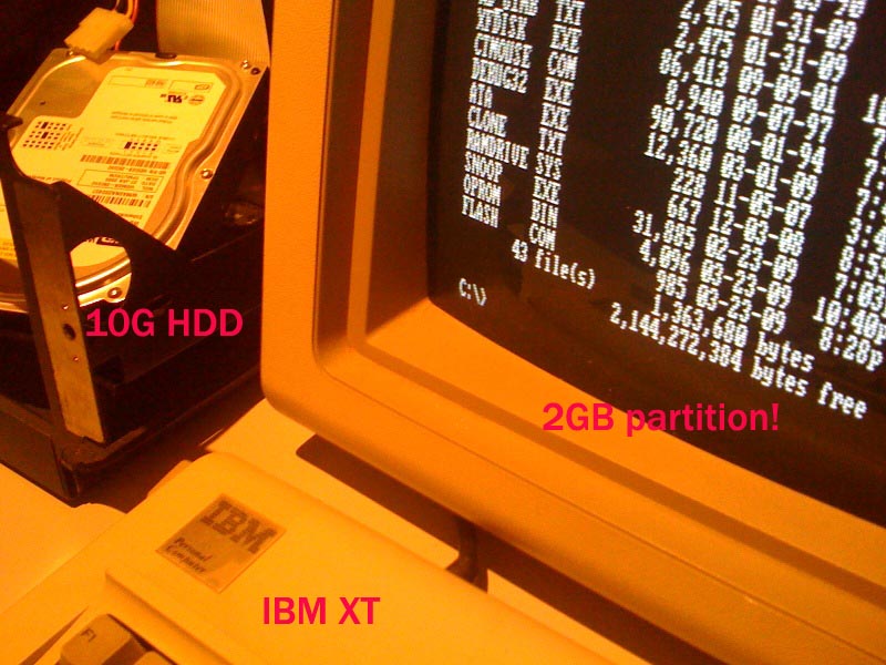
And, here's a picture to brighten everyone's day:
xtboot!.jpg


yep, I BOOTED to that sucker.
 
I do!

Jameco doesn't sell the ISA version!! They only have the PCI 9203 in their catalog. We need the 9202.

Are the specifications with the measurements in that PDF file enough for you to go off of for the PCB mounting holes, or should I actually get one and ship it to you? I may also have one among my scrap pile that fits the measurements of the one in the PDF file. lemme look.
Lemme also investigate the IRQ requirements. Currently we're not even using interrupts, so this is rather moot!

Hi Hargle! Yes, I need the actual bracket part to make the dimensions on the PCB. I don't know where the holes are supposed to be on the PCB. All the data sheet tells me is where the mounting holes are on the bracket relative to itself.

This is almost a chicken and egg kind of problem which is why I am proposing to make the cardboard mockup. I'll install the bracket in the test station and the cardboard mockup in an ISA slot. Then mark on the mockup where the holes are supposed to be on the PCB. I'll make the diameter of the holes large enough for a little wiggle room but still a snug fit. Hopefully that'll be close enough.

Maybe someone has a better idea?

As for the IRQs... I don't need them either but somebody was saying something about the Tandy needing special IRQ support. As long as they are present on the 8 bit ISA slot its doable. I'll just put on some jumpers for the usual suspects... 2, 3, 4, 5, & 7. If we are doing a PCB respin this shouldn't be a problem to add.


And, here's a picture to brighten everyone's day:
xtboot!.jpg


yep, I BOOTED to that sucker.


Nice! Excellent work!

Thanks and have a nice day!

Andrew Lynch
 
How does this design deal with drives that are very fast (8 bit ISA bus cannot move much data), any issues with this?
 
And, here's a picture to brighten everyone's day:

yep, I BOOTED to that sucker.

This is a beautiful sight. It brings tears to my eyes. Hats off to Hargle and Andrew. As for IRQs, 2, 5 and 7 would be a dream, but I'm not above cutting in a "field patch" if I need to.
 
This is a beautiful sight. It brings tears to my eyes. Hats off to Hargle and Andrew. As for IRQs, 2, 5 and 7 would be a dream, but I'm not above cutting in a "field patch" if I need to.

Yes, WELL DONE, gentlemen.

My compliments to the "chefs".

I have to agree with Andrew. Positioning of the bracket is critical. If it's out a little too much, the card may not sit in the slot right, may be tilted to one side or the top of the bracket may not come down enough to sit on the backplane well enough to screw it down without bending it.
 
How does this design deal with drives that are very fast (8 bit ISA bus cannot move much data), any issues with this?

I've not seen any issues, but then again, I *just* moved the card over from my 486 development station to the XT last night, so timing stuff might creep in now. There were no issues that I saw on my 486, and I was playing around with everything from 600MB drives up to 250G drives.
There may be some tricks I can do to the drive as well, like forcing the drive into PIO 0 mode (the slowest) by using a set features command at startup. We'll just have to see how things go during this phase of the debugging.

---------

Looks like andrew has the IRQ request jumper block in the works already, so that shouldn't be a problem. As I've said, right now, the card isn't using *any* IRQs, which does impact performance, but should make the device work on any platform. I will have IRQ and non IRQ versions of the BIOS available.

---------
I'll order a few brackets.
First I need to get ahold of my IC vendor to see if he can put together a complete list of components for the card, and if not, I'll add whatever he's missing in my shopping cart. I should be able to get an order in by the weekend I'd think.
 
I did some looking on Google and it looks like the 8 bit bus has a bandwidth of 7.9Mb/s, Now I don't know if that's true with the 5150.

The Hard drive I plan to use in my final setup is a quantum pro drive 271MB. With two 10MB's under dos 2.1

Info about the drive here:

http://stason.org/TULARC/pc/hard-drives-hdd/quantum/PRODRIVE-LPS-270-AT-271MB-3-5-SL-ATA2-FAST.html

Under the "Data Transfer Rates" near the bottom of the page it says "Data is transferred from the disk to the read buffer at a rate up to 5.8 MB/s in burst. Data is transferred from the read buffer to the AT
bus at a rate up to 4.0 MB/s, using programmed I/O without IORDY, up to 11 MB/s using programmed I/O with IORDY, or at a rate of up to 13.0 MB/sec using multi-word DMA."

Not sure what all the means but it sounds like if you use it without IORDY then it's well under the 8 bit bus bandwidth. I think if a person use's a 1gb and under HDD, I don't think there will be any problems with speed on the 8bit bus...

But I know nothing really, just rambling!
 
Last edited:
I did some looking on Google and it looks like the 8 bit bus has a bandwidth of 7.9Mb/s, Now I don't know if that's true with the 5150.!

I do not think it is. That 7.9MB figure assumes a bus speed of 8.3MHz. The 5150 runs its bus at 4.77MHz because it is really just an extension of the 8088 data bus. Therefore, the bandwith cannot be greater than 4.77MB/sec. However, on the plus side, there are few wait states to worry about here.

Those numbers refer to the drive being run on a more modern IDE controller and through a faster bus. Fast ATA is almost always implemented on faster buses, VLB and PCI. Programmed I/O is something that was introduced when 286 processors were recognized as efficient enough to support that method of transfer. 8088 processors must rely on 8-bit DMA transfers, which are no speed demons.

I don't claim to know much either ;)
 
Nice work gentlemen, truly impressive.

Now that it appears that you have everything in order, do you have any idea when my Acculogic sIDE card will be returned to me?

Thank you.

bobwatts
EartH
 
Hi! I updated the schematic and PCB layout with the changes as far as I can go without the bracket. Attached is a notional PCB layout.

The design with probably it will be something close to this with the bracket holes repositioned and with traces routed. This should give you a good idea of the PCB layout. The PCB layout favors trace routing and will include a silkscreen layer with some descriptive labels etc.

Please post your comments, questions, suggestions, etc.

Thanks and have a nice day!

Andrew Lynch
 
I haven't been following this thread as I'm not looking at modding any of my vintage stuff (yet) but I've just read over what you've done and I have to say "WELL DONE GUYS!"

Tez
 
Same here! I've still got enough MFM drives & HDCs to keep my few XTs & clones going for a while so I don't need one, but I can still appreciate this terrific cooperative effort!

Fascinating reading, watching something like this (and Andrew's N8VEM project) come to life and grow; one of the things that really makes this hobby special.

Great stuff!
 
Nice work gentlemen, truly impressive.

Now that it appears that you have everything in order, do you have any idea when my Acculogic sIDE card will be returned to me?

Thank you.

bobwatts
EartH

I'm still testing everything IDE with my Acculogic.

So far the only CF card that will work with it is a 128meg.

256 CF didn't work, a 2 gig CF didn't work, waiting for a 512meg one to come in, probably won't work, but never know till you try.

:>
 
I am not in to modding my vintage stuff yet either, however until someone finds a way to repair old dead MFM drives such as the ST-412, I am going to make that choice to retire my working drives so 5 or 10 years from now it will still be working. and someone like your self mike that makes the choice to keep useing the MFM drives will eaither have to use the IDE card or not have any MFM drives left, they are all running on borrowed time!

I haven't been following this thread as I'm not looking at modding any of my vintage stuff (yet) but I've just read over what you've done and I have to say "WELL DONE GUYS!"

Tez

Same here! I've still got enough MFM drives & HDCs to keep my few XTs & clones going for a while so I don't need one, but I can still appreciate this terrific cooperative effort!

Great stuff!
 
Nice work gentlemen, truly impressive.

Now that it appears that you have everything in order, do you have any idea when my Acculogic sIDE card will be returned to me?

Thank you.

bobwatts
EartH

Well, Bob, due to circumstances, I'm actually just going to be shipping the card to Hargle tomorrow, so, when he's done, it'll be returned safe and sound.
 
<snip>...someone like your self mike that makes the choice to keep useing the MFM drives will eaither have to use the IDE card or not have any MFM drives left, they are all running on borrowed time!
So am I ;-) It's just a tossup who/what goes first, but if I outlast the last MFM drive I'll be happy. On the other hand I hope that by that time I'll have managed to get rid of all this junk, and I've also made a solemn vow to not spend another cent on more "stuph."
 
Last edited:
Back
Top