• Please review our updated Terms and Rules here

Mono composite screen issues

tezza

Veteran Member
Joined
Oct 1, 2007
Messages
4,731
Location
New Zealand
Hi guys,

I'm working through my System 80 haul at present.

I'm wondering if anyone has any thoughts on the symptom below. This composite monitor shows an image, but there are flickering lines across it as in the picture below. The text is not that clear either. Turning up the brightness and contrast also causes the characters to break up somewhat and lose further clarity.


2010-09-15-faulty-ds-monitor.jpg


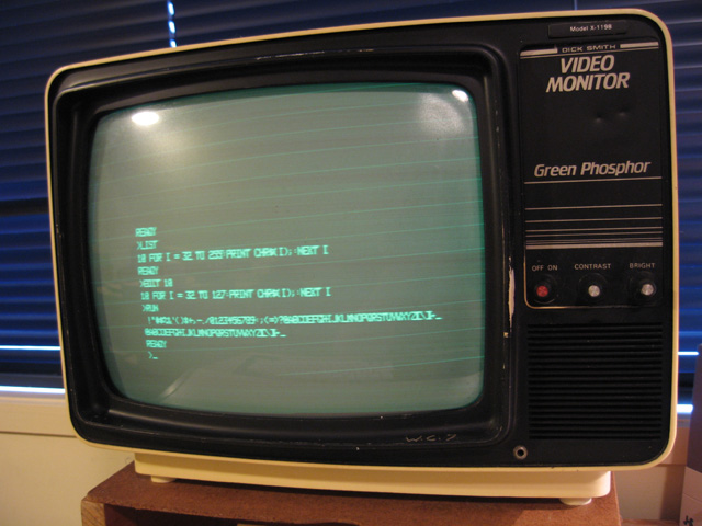
I've got two of these. One works fine but this one does not. I'm not familiar with monitors and if I can't fix this one I might pass it on. If anyone recognises the symptom though, or just has some thoughts about it I'd love to hear them.

If it's a quick fix, I'll give it a go.

Tez
 
Hi
Those are horizontal retrace lines. Usually it is that the contrast
and brightness are turned up too much. This is often because
the tube has poor emission but could be a loss of amplitude of
the video signal along the line. This is often caused by a bad
emitter resistor bypass capacitor or some such.
You might trace the video path on both units and use and
oscilloscope to compare. It is good to have both units to compare.
Use caution around the tube as there is the nasty second anode
as well as the first anode on the pins of the tube.
The video path is easest traced backwards from the CRT.
It would be connected to the cathode( not sure which pin that is ).
Dwight
 
Hi
I just did a little looking. Pin 7 is the cathode.
Pin 3 is what I call the first anode
but schematics call it G2. It is usually around 400V. It is pin 3.
Pin 4 is the focus grid and it is usually around a couple hundred volts as
well. Usually pin 3 will have some extra shielding for voltage.
Stay away from these pins, just follow pin 7.
Dwight
 
There's also a fair amount of what looks like underscan--you may want to check the power supply voltages.

But Dwight's right--you get those lines during the vertical retrace interval as the beam moves back to the top left corner of the screen after having painted a field. Since horizontal sweep is still running, you see lines. Normally, this is taken care of by a "blanking" circuit that turns off or dims the electron beam during that interval.
 
Hey Tez...

I'd treat that one like an old arcade monitor. Shotgun the electrolytic caps and resolder the cracked joints... power it up and check. Adjust the screen control and focus if they are available for adjusting on or near the flyback...

If it's still ugly, then it's time to troubleshoot.
 
Thanks for the comments guys. I'd ponder them and maybe disassemble and have a go.

Dwight, where do you get the schematics for these?

Tez
 
Hi
You can look at some typical schematics and get a general
idea. There isn't too much difference between different ones.
That is why I suggested tracing back from the cathode pin.
There should be a video out put transistor that is usually
an emitter follower. This connects to a transistor in the more
typical common emitter. This is where they usually have
and electrolytic bypass capacitor. Before that is where
the sync separator is. This is also where the blanking is
handled.
Look on bitsavers.org under ball for some typical circuits.
Dwight
 
There's also a fair amount of what looks like underscan--you may want to check the power supply voltages.

But Dwight's right--you get those lines during the vertical retrace interval as the beam moves back to the top left corner of the screen after having painted a field. Since horizontal sweep is still running, you see lines. Normally, this is taken care of by a "blanking" circuit that turns off or dims the electron beam during that interval.

Sorry to activate this old thread but I've just found my way back to this problem.

I don't have schematics for this mono monitor (actually a portable TV with 1/2 it's components missing). This TV also has a 12V socket, presumably for operation with a car battery. I have two of these ex-TV monitors, one works well, the other gives the symptoms shown.

Anyway, I measured the DC voltages onto the board out from the 240 mains transformer.

Good Monitor = 11.5 V
Bad monitor = 8.4 V

Seems a little low to me! Would this give the underscan you suggest Chuck?

Tez
 
I don't have schematics for this mono monitor (actually a portable TV with 1/2 its components missing).
I like the huge label taking up the space where the channel knobs would be. :) Are the speaker and earphone jack still functional, or were those taken out as well?

My father's IBM Portable PC always had visible retrace lines on its little amber CRT when you turned the brightness all the way up, even when it was brand new -- but the text was very sharp and clear, and the lines were steady, not flickering.
 
S
Good Monitor = 11.5 V
Bad monitor = 8.4 V

Seems a little low to me! Would this give the underscan you suggest Chuck?

That'd do it, Tez. I wonder what things would look like if you tried operating the set from a battery charger or other source of 12 volts. If that cleared the problem up, we'd certainly know what the cause was.

Since this is a TV set under the wraps, did you happen to find a chassis model number for it anywhere? That might help to locate a schematic for it.

Yes, I certainly had a good look Chuck, but to no avail. Samsung is written on the tube. However, we are talking Samsung back in 1981 when it was a small virtually unknown (Korean?) company. It's a pity there seems to be no docs as the board is extremely well labelled with component numbers and symbols. Half the board is empty of course, where things like TV tuners would have gone in. :)

The nice thing about these monitors is that Dick Smith left the audio amp in and added an input socket for all those System 80 (i.e. TRS-80 M1) games with sound effects :)

I'll see if I can find a 12V source with the necessary amperage. I could always swap the transformer in the good machine over to the bad one I guess. A bit of soldering but not much.

Anyway, I'll let you know how I get on. I'm not sure how easy it will be to get a replacement for the transformer, even if that does turn out to be the problem.

Tez
 
Most likely it's not the transformer but whatever the power supply uses for a regulator. I'd first check for the usual suspects--bad diodes, crispy power resistors and bad semiconductors. While failure is not unknown, transformers themselves don't fail often.
 
Sorry guys I should have clarified.

These voltatges are AC and are straight from the transformer. They attach to the circuit board at two points conveniently labelled "Ac input". The regulators, doides and other such things come after this. The only thing between the 240V AC on one side of the transformer and the 11.5v AC line as it enters the circuit board from the other side (or , 8.4v AC in the case of the broken one) is a fuse.

It's a little hard to see, but I can only spot two wires going exiting the transformer (both 11.5V AC on my good one). Should there be more and would they be important? Without a circuit diagram I'm flying blind here. I'll disassemble if I need to, but at the moment (unless I've missed something) this transformer seems to be the only thing between the 240V input (same on both machines of course) and a clear difference in AC output.

Tez
 
These voltages are AC and are straight from the transformer. They attach to the circuit board at two points conveniently labeled "Ac input". The regulators, diodes and other such things come after this. The only thing between the 240V AC on one side of the transformer and the 11.5v AC line as it enters the circuit board from the other side (or , 8.4v AC in the case of the broken one) is a fuse.

Possibly something on the input side of the power supply is loading down the transformer. That might make something hot. Something like a shorted diode in the full wave rectifier or a bad filter capacitor or something.

One thing to try might be to unsolder one of the transformer leads to the board and see if you get > 11.5 VAC open circuit reading. That would indicate the transformer is OK.
 
Definitely lift one lead of the secondary, power the thing up and see if it still runs hot. If so, yeah, it's probably the transformer. Fortunately, it shouldn't be hard to find a replacement.

If it's not hot, then the fault lies in the rest of the power supply. What you're going to find at a minimum is a bridge rectifier (or 4 diodes in a bridge configuration) and a filter cap (if that's bad, that'll certainly drag you down). There might also be some sort of regulator, although that part may be after the 12V jack.
 
Hi,

Lifting one of the wires coming from the transformer and measuring it shows 16VAC! (as opposed to 8VAC when connected). The transformer doesn't seem to get hot at any time. So you're right, it might be something pulling down the power.

Here is a photo of the top of the board. I think I can see the four diodes you mention Chuck. Is that the bridge rectifier? As you can see they don't look in good shape.


2010-10-24-power-section-DS-monitor.jpg


I don't have any spare diodes like this at home and tomorrow is a public holiday, but I could replace them later this week if you think they might be the cause.

Voltages on the AC input seem to drop a volt or so on BOTH monitors when they warm up. I'm assuming this is normal.

For the hell of it, I measured some voltages at the top and the bottom of the four diodes

AC voltages at the top (from left to right) are.
Good monitor: 10.4, 10.4, 10.2, 9.6
Faulty monitor: 7.6, 7.6, 7.3, 7.3

DC voltages at the top (from left to right) are:
Good monitor: 2.5, 2.05., 2.05, 2.06
Faulty monitor: 0.15, 0.15, 0.15, 0.15

AC voltages at the bottom (from left to right) are:
Good monitor: 23.8, 0, 0, 23.8
Faulty monitor: 16.6, 0, 0, 20.5

DC voltages at the bottom (from left to right are:
Good monitor: 11, -6, -6, 11
Faulty monitor 7.6 -8.1, -8.3, 9.6

I also measured the values across the large white 7W ceramic resistor. Top is 6VDC on the good monitor, 8.5 VDC on the bad monitor. This gets hot on both monitors but it gets much hotter on the faulty one.

The large electrolytic is a replacement so brand new.

I also measured voltages on that regulator-type transistor (SA 634 Y III) although I'm not sure if it's part of the circuit. Voltages on the non-ground pins are very similar for both machines.

There is another regulator-type transistor (SA 634 Y II0) hiding behind that large heat sink. This DOES seem to be part of the circuit. Interestingly the middle leg didn't seem to be ground. It showed some resistance when measured across. Consequently I took some voltage readings from the middle leg as well as the other two. Measurements were.

Top leg AC - Good: 11.2
Top leg AC - Faulty: 11.2
Top leg DC - Good: 5.38
Top leg DC - Faulty: 5.38
Middle Leg AC - Good: 23.8
Middle Leg AC - Faulty: 20.5 (a difference here)
Middle Leg DC - Good: 11
Middle Leg DC - Faulty: 9.6
Lower Leg AC - Good: 9.9
Lower Leg AC - Faulty: 9.8
Lower Leg DC - Good: 4.7
Lower Leg DC - Faulty: 4.7

Any comments on any of the above welcome.

Tez
 
Tez,
You are getting very handy with a DVM. Without a schematic we are all at a disadvantage. The resistor in the faulty monitor is dissipating 3.3 Watts while in the good system, it is only 1.6 Watts, so I bet it gets hot. I can't make much out of the voltage readings yet, but what was your measurement reference? Was the black probe on chassis ground?
 
Tez, would it be possible to flip the board over and get a shot of he foil side of that board in the same corner? I'd like to put together a picture of how things are connected.
 
Just a guess, but going by the location of that resistor and the fact that it's hotter than the other, I'd be inclined to suspect that the problem's downstream from the diodes; what does the bottom of the resistor connect to?
 
Back
Top