modem7
10k Member
Turned out to be straightforward.I need to work out now how to flash the AM29F040 (fitted to XT-FDC) from DOS.
As far as I'm concerned, the 'Optional ROM Drive' section is operating as expected.
Turned out to be straightforward.I need to work out now how to flash the AM29F040 (fitted to XT-FDC) from DOS.
At post 173, Chuck wrote, "I can add that the external drive connector (DC37F) works just fine with my external drives."I think all the major subsystems have been tested now except the external floppy drive connector ...
I'll look at that once I work out why my XT-FDC card isn't functional in my IBM AT (5170).... and the 8" floppy internal connector.
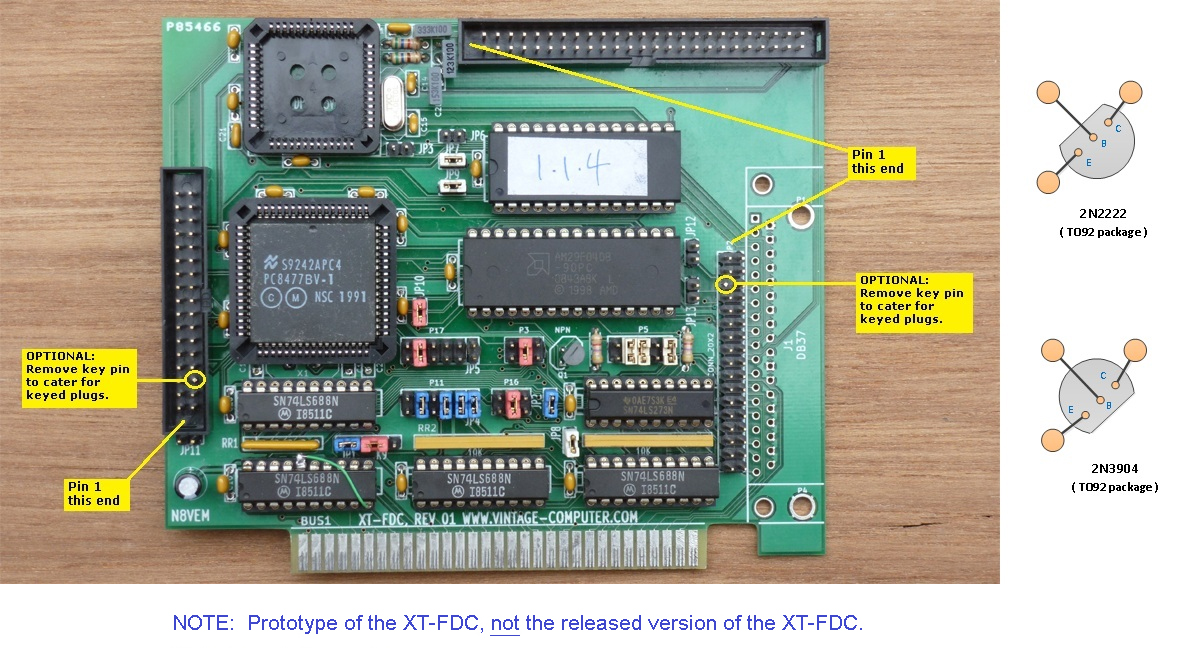
Per http://www.minuszerodegrees.net/xtfdc/photos.htmAre there any other changes except for the 7 noted earlier?

To me, that looks like he had a 5-pin resistor SIP for use in position RR1 rather than a 6-pin, and added a standard quarter watt resistor to compensate.nestor i see you forgot to do the fix on the address decoder.
Or is that resistor it?
To me, that looks like he had a 5-pin resistor SIP for use in position RR1 rather than a 6-pin, and added a standard quarter watt resistor to compensate.
The question remains. Has the decoder fix been applied?
How about I post you a PC8477BV-1 (free for prototype testers)? It should be thin enough that I can get it through as a letter. PM me your postal address in Spain.You are right I replaced all parts trying to discard any failing component but I only had a spare 5 pin resistor SIP, so I put a in the empty hole a standard resistor tied to VCC.
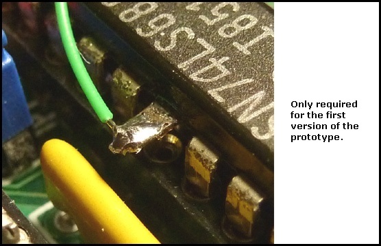
The decoder fix is applied: I cut the socket pin 16 and isolated its PCB hole so the pin makes no contact with it. Then I soldered a wire from the socket pin 16 to socket pin 17. As this mod is made under the socket, it is almost invisible.
Ok, PM sent.
Current status: The floppy disk LED lights up when it should and I can hear the head motor noise when floppy seek tests are performed... but any access will return a error ("Drive not ready" / "General failure" from DOS, 02h or 80h errors from XTIDE Universal BIOS boot).
At the moment I think there are two possibilities that can explain the troubles:
-PCB defect (shorted traces or similar problem). I will check deeply with a continuity tester.
-82077AA-1 incompatibility. I have downloaded the datasheet and seems pretty similar to PC8477BV-1... but maybe there are small differences.