NeXT
Veteran Member
Being fed up with how much standalone readers cost I'm building my own. The basic idea works like this:
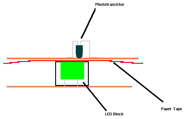
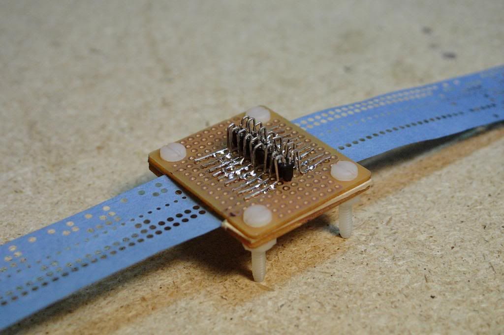
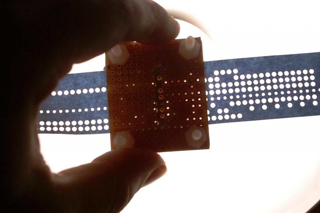
The phototransistors are arranged in a line and each one can see through a hole in the perfboard. These hole spacing is identical to that used on regular 8 hole paper tape.
Underneath the paper tape is a block of LED's that shine up and trigger the phototransistors when a hole is present for that bit in the tape.
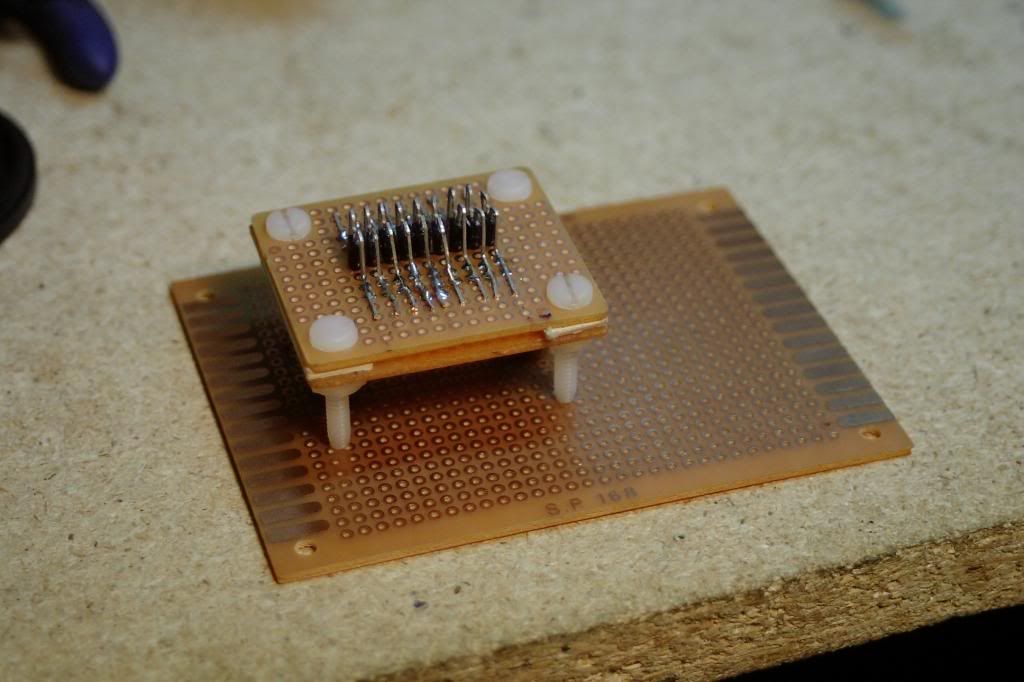
This could also be reversed where the light source is above and the bed of phototransistors is below. Might be more handy if I could somehow hinge the top for easier tape loading. The whole final assembly is then soldered to another perfboard with the rest of the logic.
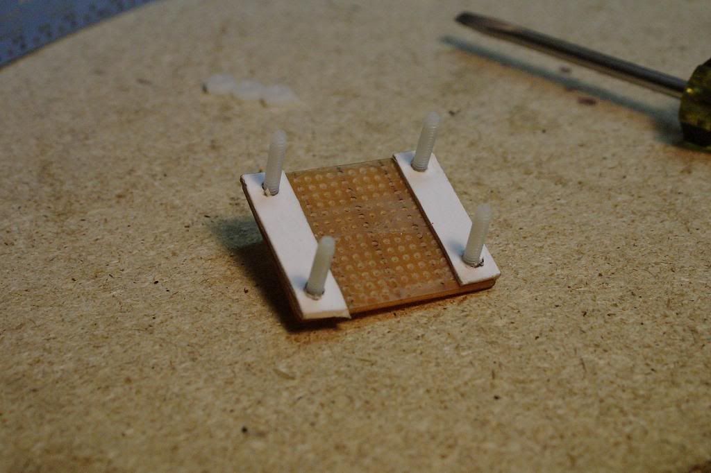
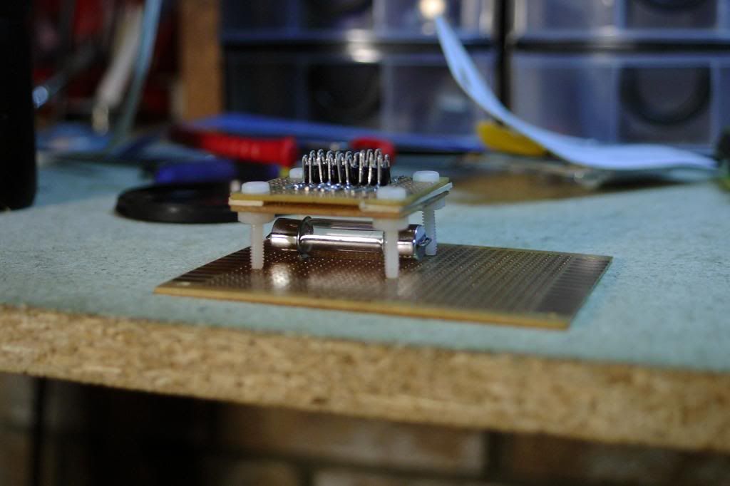
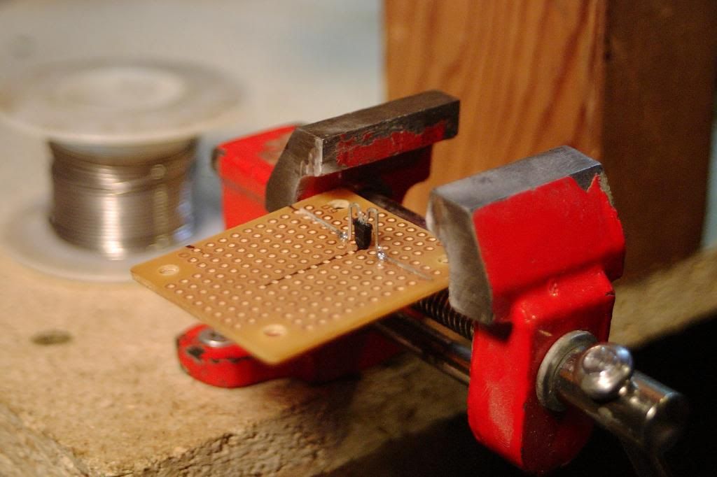
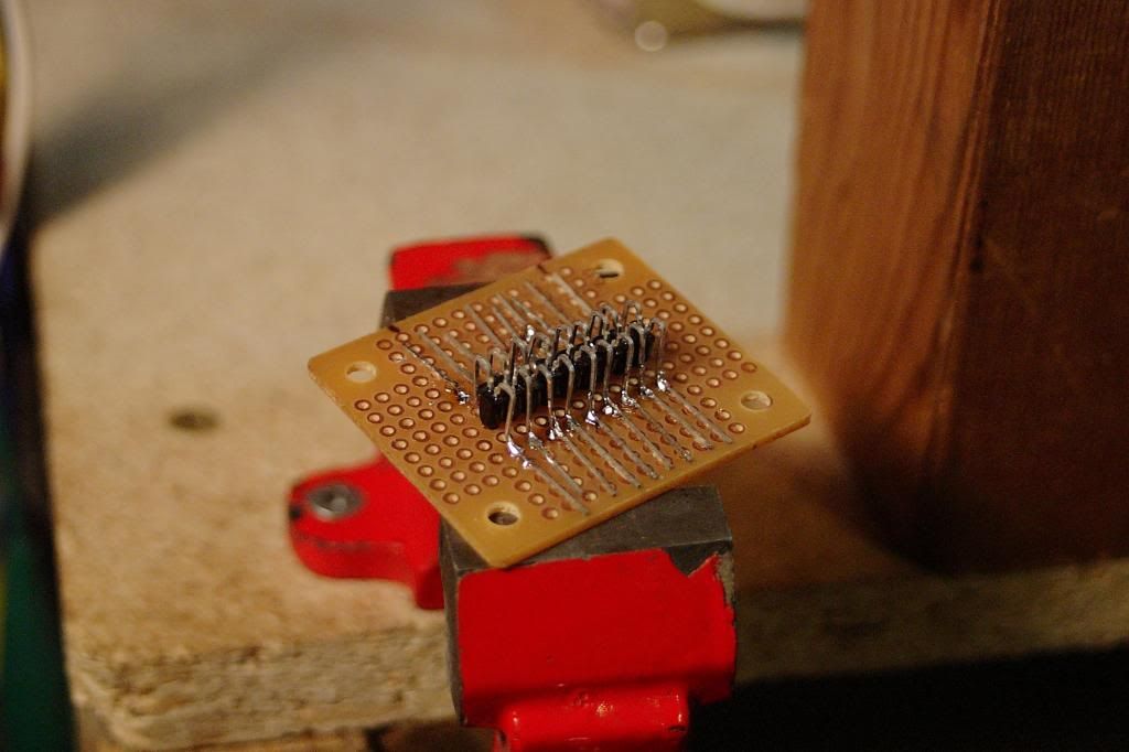
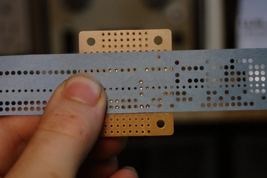
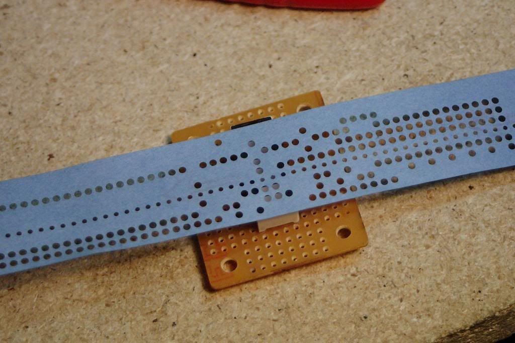
So far this is what I have done.
From there I run into a snag. I don't know how to keep the paper tape aligned. It will need some sort of guides to prevent it form shifting to the left and right and once they are fitted they can't move.
The other issue is the LED block. It has to sit in between the perfboard sandwich with the guides and the paper tape. I don't trust it having enough light to go through another set of perfboard holes. It can't be used as part of alignment with the paper tape as it's shifted to one side of the tape by almost 2mm.
Any ideas?
The phototransistors are arranged in a line and each one can see through a hole in the perfboard. These hole spacing is identical to that used on regular 8 hole paper tape.
Underneath the paper tape is a block of LED's that shine up and trigger the phototransistors when a hole is present for that bit in the tape.
This could also be reversed where the light source is above and the bed of phototransistors is below. Might be more handy if I could somehow hinge the top for easier tape loading. The whole final assembly is then soldered to another perfboard with the rest of the logic.
So far this is what I have done.
From there I run into a snag. I don't know how to keep the paper tape aligned. It will need some sort of guides to prevent it form shifting to the left and right and once they are fitted they can't move.
The other issue is the LED block. It has to sit in between the perfboard sandwich with the guides and the paper tape. I don't trust it having enough light to go through another set of perfboard holes. It can't be used as part of alignment with the paper tape as it's shifted to one side of the tape by almost 2mm.
Any ideas?
Last edited: