• Please review our updated Terms and Rules here

Paper Tape Readers

Where the heck are you looking where readers are $50-$75? The only place I'm aware of that has them run them in the $150-$300 range. At that rate it's cheaper to make your own serial reader.
 
Search eBay for "Tape Reader". e.g. item 171049693027

I've got one around somewhere.
The problem with these is the feed roller. You'll have to change it out since it's probably turned
to goo or is rock hard. At $50, though it's worth it just for the tape path, photosensors and lamp.
 
I've got one around somewhere.
The problem with these is the feed roller. You'll have to change it out since it's probably turned
to goo or is rock hard. At $50, though it's worth it just for the tape path, photosensors and lamp.

I see they list them as working with a warranty, never mind..
 
What resistor are you using to pull down/up the phototransistor? obviously the bigger it is the less current needs to flow to give a logic 1, so the less light is needed to make a logic 1

I couldn't see any resistors on your board. if it was me building it the transistors would all be commoned to ground, there would be a bunch of resistors to Vcc and the outputs would be on their way to a schmitt trigger input. & I'd be looking at running about a milliamp through the transistors when on.
 
Search eBay for "Tape Reader". e.g. item 171049693027

Thanks for confirming that ebay's "we'll email you when something you are searching before comes up for sale" doesn't work for me. I was wondering why one day all my searches suddenly stopped. I have not seen an email since 2008. Okay, so I see Fanuc units will at the least give you the feed motor, optical jig and if you're lucky the control board for $100. I'll keep that in mind for when I want to setup another reader on something but for now I'll stick to my little project.

There's no resistors yet. There's not a lot of anything besides the phototransistors soldered down right now. I'm simply attaching ground to one side of a phototransistor and poking at the other with an HP 545A logic probe until my logic analyzer arrives. If you shine a proper light source at one, the light on the probe goes out and the line goes LOW. Obstruct the light source and the light illuminates and the line goes HIGH.
 
Last edited:
Yeah, but you're only getting the photovoltaic effect from the PT; best practice is to use a pullup to a known voltage (say, 5V) through a 5-10K resistor. That will cause the PT to operate in the "saturating" mode (either fully on or off). If you use a lower value, say, 1K resistor, the PT should operate in the linear mode, where output is proportional to the incident light.

I'm thinking that you want the all-or-nothing mode.
 
I'll be honest and outside of the construction of the block I'm still in the dark about the electronics. I tried duplicating a Raeco TPR-1 years ago and that never went beyond a half milled block of aluminum. I'm literally learning the rest right now as I roll along due to a lack of documentation on how the homebrew units were constructed. There's just a lot of finished pictures. The fact that a resistor would of helped might of been nice to hear earlier before I ordered more components. Is there any other helpful information I have not been told?
 
The fact that a resistor would of helped might of been nice to hear earlier before I ordered more components. Is there any other helpful information I have not been told?
How on earth are we supposed to know what you know and what you don't know, especially something as basic as a transistor switch? Why don't you Google 'phototransistor circuits' and learn instead of bitching because we can't read your mind.
 
I'm sorry. I want to learn but I just don't know what I'm doing. Call my rorypoole but I am at least trying.
Okay, so looking at basic circuits I see that yeah there should be a resistor in the circuit as well.
3533b.gif

Let me run a few tests and get back to you.


Edited: The bulb is still useless but LED's are now working.
 
Last edited:
For what it's worth there was a capable review of the Oliver Audio Engineering OP-80A paper tape reader in the December 1977 issue of Kilobaud magazine that had a block diagram of how it worked as well as some source. Interestingly, it used 555 timers to trigger the logic thresholds.
You can find it at archive.org here http://archive.org/details/kilobaudmagazine-1977-12

For a workalike I would consider using Schmitt trigger gates to get a definate logic level change. There is a really great article (with simple circuits and animated outputs) on understanding these at http://www.doctronics.co.uk/4093.htm

Lastly, if I had a paper tape that would not read well with an optical reader I would lay out the tape upside-down on a sheet of cardboard and give it a light spray of matt black paint along its length from a rattle can. I can't forsee a light coat doing any damage to the tape but, as always, trying it on a test sample first would be a good idea :)

Steve.
 
I looked over the OP80A before (there's a full website with documentation and schematics here) and again a parallel reader won't work for me. On the other hand I noticed they included instructions for modifications to make it a serial interface by tacking it onto the 2502 UART but that's a $20 chip that belonged at the time on the MITS 88-SIO board so there's more than just the chip I would have to deal with on top of the serial modification leaflet being missing so instead I'll do what chuck said and use just an MCU and MAX232. Like mentioned before I stockpiled about a half dozen PIC16C's and I can program them once I finish this damn chip programming station.

So for now I went and bought a few 4093's and a few MAX232's to replenish my stock (they're 50 cents each on ebay).

Hi NeXT,

I always wanted to do this! I missed my chance to get one of those Oliver Audio OP-80 so many years ago, and they are now quite rare.

Anyway, what is the part number of those photo transistors? Are they available at Jameco or Digi-Key or Mouser?

Thanks,
smp
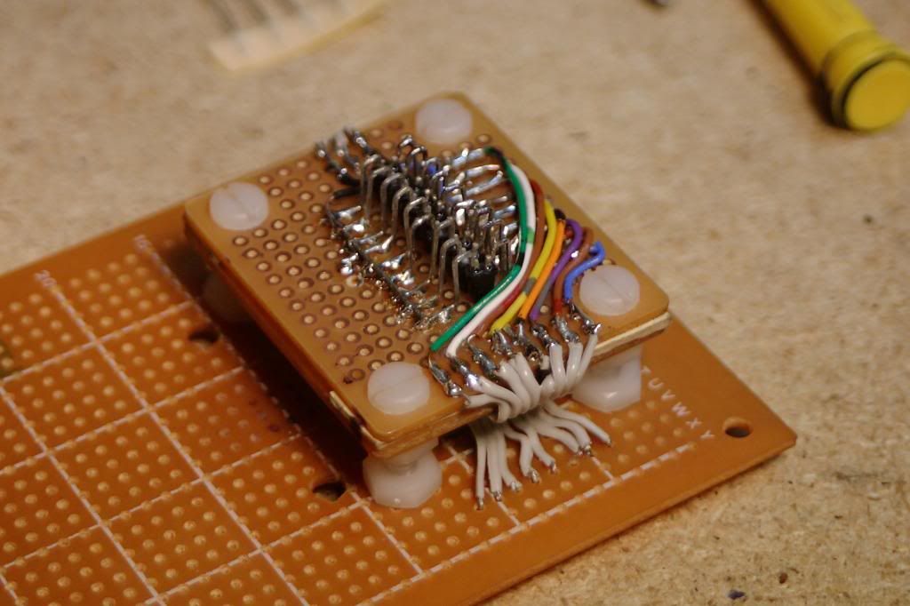
Didn't see this until now. Call it trouble but I literally bought the cheapest phototransistors I could off ebay (the datasheet for mine specifically are on page 2) because I don't have a credit card to pay for Digikey or Mouser orders. Don't forget to dremel the sides so you can sit them next to eachother. :)
 
Last edited:
...I noticed they included instructions for modifications to make it a serial interface by tacking it onto the 2502 UART but that's a $20 chip that belonged at the time on the MITS 88-SIO board so there's more than just the chip I would have to deal with on top of the serial modification leaflet being missing

All I have to say is, old issues of Kilobaud are such a goldmine. "Who Needs a UART?" - parallel to serial with four simple chips (page 108 with schematic) http://archive.org/details/kilobaudmagazine-1978-08

If you're after tiny phototransistors and matching IR LEDs, why not rescue some from an old (ball) mouse? I'd hazard a guess that a lot of folks on this forum would have a few in their junk stash. Small IR LED / PTs are also common in old laser printers, where they are usually in a single interrupter unit. Can't be more frugal than that I reckon :)

Steve.
 
Slow progress but still being worked on. Installed the IR LED's which work a lot better. Also committed the optic block to the main PCB by connecting everything.

CGS_0218.jpg

CGS_0219.jpg


There's been a bit of an issue with resistors as of right now. I have to hold back on ensuring the block works until I order another set of 47K resistors, then I need to work on getting the LED intensity just right. I'm sure it might be better if I was using variable pots but you work with what you got and save yourself the two week wait for the mail.
I found a very tiny electric RC motor tail rotor that you could slow down nicely. I might consider some sort of mechanism to pull the tape through that uses either a rubber wheel or a proper size sprocket. I need to figure out first how to mount the motor. The idea was to go direct drive.
 
Might not be important but some light screening between the phototransistors might be needed. Whilst you want the IR to go in a straight line from emitter to detector, in reality it gets sprayed all over the place. This continual background light might make setting up the phototransistor bias point difficult. Something as simple a a black permanent felt pen over the whole phototransistor other than the very top of the dome might do.
 
If anyone is interested then ebay 390676804061 is a paper tape reader, 8 channel. It looks like the one on the Siemans TTY.

Price seems rather silly to me, but make an offer, I got a store from them for half the asking price.

Note that this is in the UK.
 
I would think it better to find some clear photo transistor, even IR ones.
Use a visible red LED. It doesn't have to operate at the peak, just
have higher contrast through the paper tape.
Dwight
 
Back
Top