• Please review our updated Terms and Rules here

I'M Back, PDP 11/40..

Hi All;
I tried to (Just for the fun of it) plug in all the Boards, no change.. I put back in my Manual U WORD Module, and when I set the switches all to the High postion, the Ic's on my Board got very Warm (Hot).. So I turned everything off and went and got other things done.. When I got back I took out the IR Decode Board and the Timing Board, and nothing got Hot, So I put in the IR Board, and still nothing has gotten Hot.. So, the next Board to Re-Check Out is the Timing Board.. All by itself, With the U WORD Module, I can control what it puts out and make sure nothing will be caused to burn up, by the Timing Board..
Yes, the Timing Board All by itself, Does make My Module Hot when the Lines are set on High, So I have reset them all on Low or ground, and will work on each line all by itself, checking the circuitry arround that particular line..
THANK YOU Marty
 
Last edited:
Hi All;
I Found the Problem, I made a Mistake in the Wiring of my Module.. In the last 16 bits the first 12 bits were wired wrong, and the last 4 bits were wired correctly.. I had wired the Switch to the Output of the 74174, instead of to its input, So the Switch was fighting what ever the chip was doing.. And, so I had alot of heat of many parts..
Most of the bits affected, Maybe all of them were for the Timing Board..
I have 6 more corrections to do, I have done 6 already.. If these are the only mistakes in my Wiring of this Board, I will be Very Gratefull and feel very Blessed..
THANK YOU Marty
 
Hi All;
I checked the rest of them and all of them were correct.. Finished wiring the last 6 of them.. Now no more Heating up of the U Module Ic's.. So, Now I can really test the Timing Board while I am at it, as well as the IR Decode, for setting up the correct code to make it see when I use the different switches, such as Ld Addr, Dep, Exm, and Start.. As I have not been able to make Ld Addr, Dep and Exm work.. This should point to the Culprit and on which Board is the problem..
THANK YOU Marty
 
Hi All;
My Timing signals are Right On, When setting the appropriate, Clk signals, via my U Word Module.. Now to check that it puts out, signals for B and D register clock signals on that page..A whole slew of signals to check on that page of the Timing Board Schematic Before I put the Data Paths Board back in.. Page 2 of the Timing Board Schematic checks out OK..
THANK YOU Marty
 
Last edited:
Hi All;
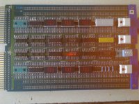
I am in the process of putting sockets, in alot of the Ic's on the prom Board, eventually everything except for the Proms will be socketed, If for no other reason, than I will be able to read the proms, without taking them out.. In this first stage I should be able to read the Pupp addresses..
I also need to figure out a bigger Power Supply for when I have all of the Boards in..
THANK YOU Marty
 
Just posting so you don't feel alone in this. I'm trying to follow along, but frankly, not completely comprehending each step. It's no matter - as you seem to be making progress.

The only contribution I can offer might be the suggestion that you create and attach some sort of monitor to the system bus to display power supply voltage status (high - ok - low) and perhaps latch "out of tolerance" variations so you know they have occurred.

I'll continue to be here, for whatever it's worth.
 
Hi All;
RSX11M, I understand Your not always being able to follow along.. Also, Thank You for Your encouragement and Fine Suggestions.. Please continue giving me some encouragement.. I need it once in a while..
Sometime I go a different Direction, Just to get away from the Path that I am on, To give me some breathing Room, And time to think about that problem.. Also sometimes, it produces something good and sometimes it doesn't.. And, it leads me down a path to a new to me problem, that I didn't know about before..
As for instance I am still not able to get the front panel switches to work, even slightly.. So, following that Path of thinking, I can follow the signal one set of signals on the IR Decode Board, which goes thru a MUX only its not there on the MUX output.. I have a set of Signals that are on my U WORD Module that control this MUX, So I tried to look at my sending the control signals to the MUX, only its not happening, and then I have had the Power Supply problem, and have not yet found "why" I can't control the MUX, so that where I am at the present.. Having to solve one problem, before trying to figure out how or why of the other problem.. And So, It looks like I am not going in any sane methodology..
Since I still don't know, What and How much on each Board got "wiped out".. It is What got spread from one Board to another and possibly over voltage that stressed out some IC's that are unrelated to the original problem.. So its finding what works and what doesn't and having everything working before I can get some of it working, type of thing..
I have a heavier Power Supply, (More Amps) and I found out what the problem was on the other one.. The Ground Connection, where I had a "tab" connector, had gotten corroded and would not conduct as well, it was causing the Machine to see 4.30 volts instead of the 5.20 volts from the power Supply.. Once I filed and cleaned it, I got the correct Voltage on the Caps of the Board.. And my power wires Don't heat up now.. Which when I could smell the insulation burning, Would cause all kind of fits, because I was thinking I had a Board Burning up, and would look for a "Hot" IC..
THANK YOU Marty
 
Last edited:
Your confirmation of the corroded power supply "return" connection supports my instinct that problems were power related. I suppose a monitoring tool may not be as important now, but please keep in mind that extensive troubleshooting simply isn't meaningful if bus supply quality is in question. It also serves as an illustration of how important loading and measuring the actual bus is.

Returning to your work... I would hate to be in the position of judging success or failure by IC heating. It leaves me fearful for your efforts. Not intending to be critical, I'd like to help you get on firmer ground. Exactly how to do that is not clear to me, which is why I haven't posted much as you work along.

I can see the sense of your approach - making a tool to directly manipulate the bus and then use it to troubleshoot boards one at a time. It's a lot of extra work, particularly proving the tool is made as you intended. So I recognize there may still be revelations yet to come about the tool itself.

Still, as you gain experience with it and other boards - you should become more effective.

Focusing on single boards that can demonstrate incorrect function will simplify the puzzle to the point of solve-ability. As long as your tooling allows you to condition all the required signals, this approach should succeed. My advice would be to refrain from introducing multiple boards until you run out of problems demonstrable with single ones.

I'll keep trying to follow along on the details as you post, as I'm sure others are too.
 
Last edited:
Hi All;
RSX11M, for the Most Part I am Not basing my looking for something Bad by the IC getting Hot.. But, since, Origionally An IC on the Timing Board was burned up along with a Trace, and it looks like some of the IC's that I have replaced on the Data Paths Board and have that burnt look or smell to them.. Then the smell of something burning make me wonder If something else is going Bad in a quick way..
No, for the most part I look at the logic that a part is supposed to give me from an input that I can control and monitor its output with my scope.. Its, just alot of Gates to go thru, I try to make (with a 1/4 inch Dot) a record of what has been Tested and has Passed, or not passed.. Sometimes the not passing is my need of a signal(s) from another Board..
THANK YOU Marty
 
Hi All;
It looks like E72 and E81 on the IR Decode Boards is OK, I at first thought that it wasn't working, But I had my clip on E97, I am using for this test pin 5 on these two Ic's, as this is an unused input pin.. So Now I will put back in the Data Paths board and see if I can get the Halt Switch signal to pass thru, for the next test, If that is Ok then I will follow it to the next stage..
I tested pin 23 on each of the 74150's and the switch that is activated passed thru to its output on pin 10.. So at least The Signals from the switches is getting This far..
2013 Views, it seems like a Good Year, to me..
THANK YOU Marty
 
Last edited:
Hi All;
I have been away from things for about a week, working on Trailer issues, and being sick.. So, I am now going to try working on it again..
I would appreciate any suggestions and such from anyone..
I have tested these places, page 2 of the Timing module, that gives me the basic timing signals.. On the Data Paths, I have replaced the 74181's and the Intel 3101's, and this area seems to work better than before.. I think some of the 3101's were heat damaged.. On the IR Decode, I can get the signals from the Various switches to pass thru the multiplexers, but no front panel functionality, with all the cards in.. Some of this might be to NOT having AC LO and DC LO.. Because when I would first power it up I could by shorting momentarily +5 to ground on the Front Panel get the Console Led to come on and then at least start would work.. Now that doesn't even work.. So, that is where things are at present.. I figure, unless someone suggests something different, since I am on the IR Decode Board that I will follow on thru from the multiplexers forward and backward, making sure that what is getting to the multiplexers is the correct signal and that after them that the selected signal keeps on going to its intended spot..
THANK YOU Marty
 
Hi All;
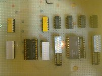
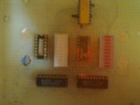
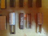
Yesterday and this morning, I wire-wrapped two circuit boards for more testing.. They are on the same wirewrap board, they just do different things.. One is for a single unit 74181, it Monitors the signals with Led's and (drivers for the Leds).. As, well as the ability to switch in a 74181 any one pin or all of the pins to the 74181..
And the other circuit is to Monitor with Leds, the Intel 3101 or 74289 Ic.. Both of these are cable dependent and are only four bits wide, so to do all 16 bits, the cable has to be moved to the correct socket, Since these both are all socketed anyway, it is no problem..
The Pictures are a bit Blurry, and I made it so the 74181 can use either the old regular wide body 24 pin socket (IC), 74181 or the 74S181 or the newer skinny 24 pin socket, for the 74AS181.. And, Yes I will be ordering some 12 position switches..
I think I may be getting Sick again, I have Never been this sick over and over, I have one errand to do yet today, but just in case You do not hear from me for awhile, you know why..

12262013915.jpg 12262013916.jpg 12262013921.jpg

THANK YOU Marty
 
Last edited:
Hi All;
I finally got around to taking out my Old Power Supply and putting in my PC style Power Supply, it has +12, -12, +5, -5, and +3.3 volts.. and it also has a DC Good line which I have wired up to the DC LO line, leaving the AC LO line tied to +5 thru a resistor, as before.. For now I won't be using the -5 and not at all the 3.3 Volt lines..
All, I have to do is to Tape up the connectors, and I can try the Smoke Test.. I will tell You If things are better or worse, or the same as before..
THANK YOU Marty
 
Hi All;
Its the same, But at least NO SMOKE !!! And I have Amperage to spare and won't starve, my +5 volt line.. Back to searching for that Big bad Ic or two or many..
THANK YOU Marty
 
Hi All;
I want to THANK Everyone, both publicly and privately for their Encouragement and Suggestion and ways for me to improve my hardware Troubleshooting skills.. I will need and always welcome ANY suggestions and information that will get me to my Goal of making this machine work..
So, to All a Happy New Year and maybe we all can get this machine running in the next year, hopefully..
THANK YOU, TO ALL Marty
 
Hi All;
I have unwired the Old Maintenance Board, and Re-arranged the Ic's and the one 10 Led DIP, and arranged the Octal Leds for two Vertical Rows to show in Octal the Pupp and Bupp Addresses.. So After I get it re-wired, I can see when I first turn on the /40 what Address is being addressed by the MicroController/Rams.. And see if it starts where it is suppossed to start and go from there..
I hope EveryOne is doing well..
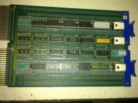
OK, Here's the Snapshot, this is unwired, but the placement is correct.. Thanks RSX11M, for asking..

01022014923.jpg 01022014924.jpg
THANK YOU Marty
 
Last edited:
Hi All;
Yea, RSX11M, a picture is worth a whole paragraph..
I am having trouble getting the first Numerical Led to show correctly, it displays a funny non-numeric character, and I have made the same circuit on my Heathkit 3400 MicroComputer breadboard, to make sure I had the correct connections.. And it displays a 7 (seven) when there is no inputs on the 74LS47 chip, which is correct, so my circuit conceptually is wired correctly.. So something else is causing the problem.. I Found it, another one of those hidden traces to ground, after taking the trace out, the display, displays the correct value.. It Now displays a 3 (three) when plugged into the computer.. Now to the next octal digit..
THANK YOU Marty
 
Last edited:
Hi All;
I got the Led's for the PUPP address wired up, and just like when I had single Led's for my display, after first starting up it shows for a first Prom Address a value of 760, then on single step 700, then 300, then 320, then back to 760.. Since the Prom Addresses only go to 377 anything at 400 or higher is a wrong Address, and 760 is definitely above 377.. Once I get BUPP wired in, I can see possibly where the (Possibly Stuck Bit might be)..
THANK YOU Marty
 
Back
Top