• Please review our updated Terms and Rules here

Argghhhhhhh! IBM 5322 went Snap Crackle and Pop!

I don't see anything wrong with polyester vs. polypropylene. Both are similar, and vastly better than paper at resisting moisture absorption. Kemet is a good brand, too.
 
I don't see anything wrong with polyester vs. polypropylene. Both are similar, and vastly better than paper at resisting moisture absorption. Kemet is a good brand, too.

Well, in my limited research the PP is supposed to be better then polyester although as you say both are better than straight paper. I placed orders at both Mouser and Digikey for the parts. I am hoping to work on them this weekend if I get everything in....
 
Well,

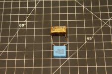
The parts arrived a bit earlier then expected. Over all things look good except for the 0.1uF capacitor which has much smaller lead spacing.

Old and Replacement Caps (Custom).jpg

Kemet/Rifa actually still sells the exact match (size and spacing) capacitor but it is a paper cap like the original. In any case the issue was easily rectified with a handy dandy Lego brick:

Legs Adjusted (Custom).jpg

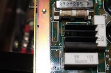
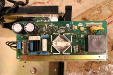
Next I cleaned up the PCB

PCB Cleaned Up (Custom).jpg

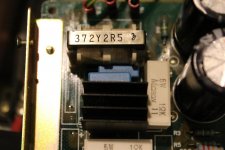
and tried out the parts:

Nice Fit (Custom).jpg

Everything looks good so far.

Jus one question before I solder these guys in - Do filter caps have polarity? i.e. does it matter how I inset these in and if it does how do I determine polarity/orientation? Thanks.
 
The particular type of filter capacitor that is the subject of this thread, is designed for AC, and therefore there is no polarity.

Thanks modem7. I know the usual caps I've replaced (the "cans") have a polarity that needs to be respected so I thought better safe then sorry...
 
Looking good

Don't worry about lead spacing. I replaced all the filter caps + the output electrolytic caps on my XT Clone. All the new electrolytics were about half the size; it's amazing what 30 years of R&D does.
 
I remember a cartoon in an old issue of Radio Electronics, I think, in which a guy proclaims to a delivery man at his door, "I said one MICROfarad!". In the background is a flatbed truck, with a gigantic axial-leaded capacitor on it marked "1 FARAD". It was funny at the time, but now 1F and larger caps are commonly available for use as clock/CMOS battery backup replacements. Go, technology!
 
I recently went through the compressor unit of my home's heat pump and replaced the motor start and run capacitors, which were about 20 years old. Even so, I had to fashion new, smaller brackets for them.

I once saw a 1F 450V capacitor many years ago as a piece of lab equipment. It was a rack-mount affair with many paralleled "Computerlytic" type caps. Even today, a capacitor of such ratings would still be fairly large.
 
Filter Caps Replaces Part 1

Filter Caps Replaces Part 1

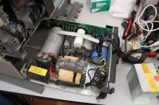
I had a chance to work on the PSU a bit more today and finally was able to replace the filter caps:

IMG_9310 (Custom).jpg

IMG_9311 (Custom).jpg

Not a bad fit and the upgrade to "blue" is fitting with the IBM legacy ;).

Since I had the PSU apart I did a bit of house keeping as well:

I replaced the insulating foam which had turned to mush. The replacement is standard insulating foam from Home Depot. Matches in size, width, and girth nicely:

20140621_191502 (Custom).jpg

20140621_191847 (Custom).jpg

IMG_9312 (Custom).jpg

I then set about testing it out. Happily the system powered on without any more snap, crack, and pop no any magic smoke escaped.

Due to attachment limitations to be continued in part 2...
 
Filter Caps Replaces Part 2

Filter Caps Replaces Part 2

Interesting enough the PSU powers up even without load (the green light comes on and the fan starts spinning).

IMG_9319 (Custom).jpg

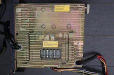
Checking out the voltages 24V was not working which turned out to be a blown fuse. Apparently this happens commonly on this PSU. The protective cage around the PSU has a cut out access to the fuse panel:

IMG_9322 (Custom).jpg

Currently the following fuses are in there:

F1: -5V 0.5A 250V GGC
F2: +12V 1.5A 250V GGC
F3: -12V 0.5A 250V GGC
F4: +24V 1.5A 250V GDL (blown)
F5: +5V 10A 32V MDL

I believe the first four fuses currently in there are Ferraz while the last one is a Bussman Cooper. My guess is that someone has changed the fuses over the years given the different series and manufacturer's of fusses. I have found replacement fuses but I am not sure that they are the correct part without the technical support manual. So here are my questions:

1. Is there a big functional difference between the GDL and GGC series. I.E. is fast vs. slow blow important or just the V/A ratings?
2. If the 24V fuse is blown, and indeed I could not get a readout at the power cable to the drives, how come the 24VDC motors on the floppies were spinning?

The system self-test reported an error on the 24V line the first time I powered it on. I am guessing this is because of the fuse. I guess another week until I can get parts and go to the next step.
 
I.E. is fast vs. slow blow important or just the V/A ratings?
Fast blow versus slow blow is important too.

The engineer probably used slow-blow on the +5V and +24V lines to accomodate a very large inrush of current occuring on those lines at power on time.
If you were to replace them with fast-blow, you may see the replacements blow from time to time.
 
I've dug a bit deeper into my machine's power supply. At first glance, the machine seems to be built for easy maintenance. The deeper I dig in, the more frustrated I get, though. Actually pulling out the power supply drawer looks like it'll involve drawing out the entire power supply and floppy disk harnesses along with it. Grr!

I haven't verified each fuse value yet, but I can see that the required fuse ratings are helpfully shown on the PCB. Fast-blow fuses have values starting with "F", e.g. "F1.0A", while slow-blow fuses have values starting with "T" (for time delay), e.g. "T1.0A".

Interestingly, I do not see any EMI suppression caps in my machine, even under the power inlet cover. My machine appears to have different power supply internals. I'll post pictures later.
 
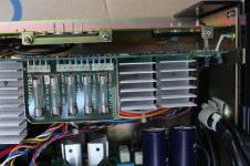
Here are a couple of pictures of my power supply with the power inlet cover removed. My machine has a different power supply than Shadow Lord's. Now that I've taken a closer look at his fuse panel picture, I can see that the fuse ratings are marked differently than mine. Ones like "1.5A-F-250V" are most likely specifying fast-blow fuses, while ones like "1.5A-T-250V" are most likely slow-blow fuses.

IMG_3077.jpg IMG_3078.jpg

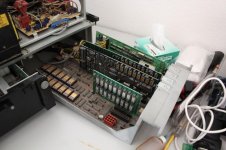
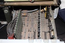
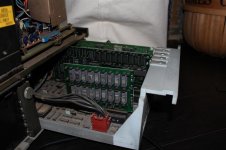
Here's my CPU drawer. Based on the pictures, mine seems to have more and/or different cards installed.

IMG_3080.jpg
 
That is very interesting. Yours has a significantly different PSU then mine. You also have more add-in cards and you have a different memory card then mine. If you don't mind what is the serial number on your machine? Also on your FDD latches do you have a 1,2 label or 1st, 2nd?

Edit: MB is different as well. On yours everything is socketed on mine only a few chips are socketed.
 
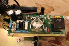
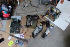
Okay. First some good news: I got the fuse in and was able to put back the PSU together. At this point the PSU seems to be supplying power appropriately without smoking or making interesting noises:

IMG_9464 (Custom).jpg

I have to put the system back together and see if this relieves the error messages I was getting.

I have to agree with NF6X. There were apparently two revisions of the 5322. I now have two 5322s and one seems to be of the same era as NF6X.

My original 5322 from this thread had a SN in the 27K. I don't have the bottom plate so I am not sure exactly what the number is. This seems to be a later revision with the witching PSU, and more items soldered on to the MB/cards as opposed to socketed.

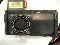
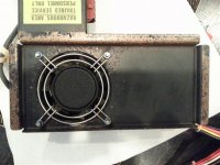
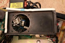
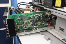
My other 5322 (which incidentally has been working fine) seems to have the same PSU as NF6X along with the MB with all socketed chips (red PCB) and the memory board with the socketed gold/purple chips:

IMG_9455 (Custom).jpg

IMG_9456 (Custom).jpg

IMG_9457 (Custom).jpg

IMG_9462 (Custom).jpg

Sorry I was a bit lazy on the last pic and did not want to take the system apart to remove the PSU but it appears to be very similar to the NF6X's earlier PSU.

Unfortunately the serial number on this one is missing so I can not verify how close it is to NF6X's.

This would make sense as the direct soldered boards would be cheaper to produce and would have been a later iteration/revision.
 
Last edited:
The second 5322 also has this board in:

IMG_9458 (Custom).jpg

This appears different from the boards in NF6X's machine so the 5322 apparently had some add-in boards (three of which are pictured in this thread).
 
I'll take some more pictures of my system when I get a chance (hopefully later this evening), to try to explore the differences between our machines.
 
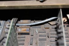
I don't have pictures ready to share yet, but I've dug deeper into my 5322 tonight. I have the card drawer fully removed and the cards out, and I'm starting to try to figure stuff out. Before I took it apart, I put numbered labels on the connectors and took pictures of where everything went.

It might be my imagination, but it sure seems like IBM went out of their way to make the design as opaque as possible to somebody without documentation and training. No silkscreen; no reference designators; what looks like customer-proprietary numbering on all of the ICs; jumpers unlabeled; even the boards just have numbers on them, with nothing that looks like a human-understandable designation. Some chips are easy to identify as "probably ROM" or "probably RAM" by size, style, parts count and arrangement. I don't think they paid NEC to custom-number the FDC chip. But pretty much everything else it indistinguishable and opaque. I haven't even figured out where the CPU is yet. Maybe the idea of having human-readable documentation on PCBs just hadn't taken hold at IBM yet, but the opacity seems so thorough as to appear deliberate to me. I would sure like to have hardware documentation for this beast!

As you'll see when I have pictures ready, my motherboard has lots of wire rework on the back. Also, two of the plug-in cards look like they have nearly identical PCBs with very different component assembly options on them; more to follow when I compose better notes.

The ROMs and a label on the back panel of the cabinet indicate a 1980 copyright date on all of the incorporated code.

Oh, and only the (apparent) ROMs in my system are socketed. Everything else is soldered down.

It might be a day or even a week before I have pictures ready to share, but I'll continue working on this fun task of comparing our machines.
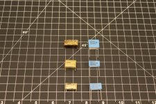
 
I am so glad I ran across this thread. A recently acquired Texas Instruments Pro let loose some smoke, but continued to operate. The PSU smelled the worse, but I could not find the offending cap as I was really focusing on the electronics. I looked again after reading through this, and found a guilty looking 0.22uf cap, split case, et.al.

Thanks much,

Ernst Land
 
Back
Top