• Please review our updated Terms and Rules here

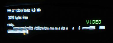
Composite picture from a CRTC PET

crock

Experienced Member
Joined
Jan 12, 2012
Messages
285
Location
Zurich, Switzerland
Gents,

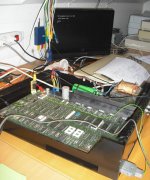
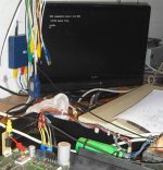
My preferred way to work on PET boards is to have the board out of the machine and hooked up to a bench supply and a small LCD monitor. This is easy using one of Matthew D'Asaro's composite adapters but they only work on the old non-CRTC PET's. They don't work on CRTC based PET's. Now, after a bit of hacking I finally managed to get a great picture on a modern LCD.

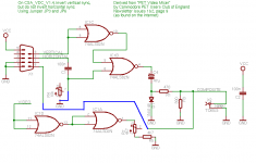
There’s three problems. First the horizontal sync pulse needs to be inverted. On a 2001 it's a positive and thus what the internal 9" monitors and the adapter expects. The 6545 also generates positive sync pulses but a standard NTSC or PAL composite signal uses a negative pulse, as do all the internal monitors in CRTC PET's I have seen, so the signal is inverted by a 74LS86 quad XOR gate at UC2. Thoughtfully, Commodore provided a couple of unmarked jumpers on the board next to UC2 to allow you to flip the polarity of both pulses. They are marked on the schematics as J1 and J2 and pull one input of an XOR gate high or low. I cut the trace to +5 and jumped it to ground, thus giving the positive pulse. No problem with the vertical sync as it’s consistently a negative pulse generated by all PET’s, although you *could* flip that with the other jumper next to UC2 if required.

Second problem is with the video signal itself, which on the 2001 is inverted (low = white, high = black), so the composite adapter inverts it again. The video signal from the CRTC PET's is already the correct polarity so I simply bypassed the NOR gate on the adapter.

Finally, the typical CRTC configuration from the EDIT ROM will not give a viewable picture on most TV’s or monitors. The standard edit ROM CRTC configurations generate a frame rate of 50 or 60 Hz, in line with the ‘local’ frequency and standards, but a horizontal frequency of 20 kHz, which is way outside the 15.625khz standard PAL horizontal frequency. Looking at all the ROMS on zimmers.net, there was one (edit-4-80-b-50Hz.901474-04_.bin) which had been modified to create the correct horizontal frequency by adjusting the number of horizontal characters. I burnt this to an EPROM and now I have a great monochrome picture on my cheap LCD TV which is quite readable in 80 columns.

The next step is to build a new version of Matthew's board which allows you to bypass the inversion of the h-sync and video signals via a jumper.

cheers, Rob
CRTC_Composite.jpg
CRTC_Composite2.jpg
 
Last edited:
Great job! I managed to use that video adapter on an 8032 by adjusting the CRTC registers with a little program I wrote. Yes, the video was inverted. I also tried running the video through a GBS8220 adapter but couldn't get it to work. Someone mentioned that one of the sync pulses had to be increased for it to work. I should also mention my "PET Editor ROM Project" which lets you assemble your own edit rom, and in that I have different settings for NTSC and PAL timings so you can mix and match different keyboard and screen combinations or even add a built-in dos wedge. Also, I wrote an interactive CRTC register editing program so you can tweak the display any way you like.

http://www.6502.org/users/sjgray/projects/editrom/index.html
http://www.6502.org/users/sjgray/projects/colourpet/cpetx.prg

Steve

PS: There is also a jumper to invert the video signal on the PET board if you don't want to modify the adapter.
 
Great job! I managed to use that video adapter on an 8032 by adjusting the CRTC registers with a little program I wrote. Yes, the video was inverted. I also tried running the video through a GBS8220 adapter but couldn't get it to work. Someone mentioned that one of the sync pulses had to be increased for it to work. I should also mention my "PET Editor ROM Project" which lets you assemble your own edit rom, and in that I have different settings for NTSC and PAL timings so you can mix and match different keyboard and screen combinations or even add a built-in dos wedge. Also, I wrote an interactive CRTC register editing program so you can tweak the display any way you like.

http://www.6502.org/users/sjgray/projects/editrom/index.html
http://www.6502.org/users/sjgray/projects/colourpet/cpetx.prg

Steve
Thanks Steve. The program's really cool but I need the PET to boot with a displayable picture without needing to load and run a program and that kernal was already set up for PAL TV's.

PS: There is also a jumper to invert the video signal on the PET board if you don't want to modify the adapter.
Really? I can't find that on my 8032080 board I have in front of me (or the schematics), any idea where?


Rob
 
This is brilliant. As a beginner to understanding video signals, this makes me hopeful for the future.

I realize that the point of this was to make PET maintenance significantly easier, but I can foresee something like this being use in a whole different way (that is if it hasn't been already). At some point down the line, it's probably going to become a serious challenge to repair/replace the existing CRTs in PETs. When that day comes, we can probably mount LCDs in the cases and use something like this to provide video with ease.
 
Thanks Steve. The program's really cool but I need the PET to boot with a displayable picture without needing to load and run a program and that kernal was already set up for PAL TV's.


Really? I can't find that on my 8032080 board I have in front of me (or the schematics), any idea where?


Rob

Out of all the possible combinations of edit roms, only two are set up for NTSC/PAL. If you have the proper matching machine then that's great. If not you have to patch your edit rom as appropriate, or you can assemble from my editrom project source. The advantage of my project is it's expandable, so if you come across some monitor that has weird sync needs you could use my "crtc explorer" program to get it working then copy the register value for use with my editrom project. That way it's available for anyone else to enjoy.

I'm sorry, I could have sworn there was a jumper, but I see now that you can invert the video signal by programming the CRTC chip "TA12" pin. The way to do that is to adjust the "video start address" hi byte register.

Steve
 
Rob,
No jumper is needed. Its an output on the 6545 CRTC. Just hit the RVS key. It sets the 'Invert' bit in the 6545 (TA12).
-Dave

OK, I forgot that the RVS key doesn't invert the screen forever, only the new data and stops when the return key it entered. So it won't do.

So one has to change the TA12 line in the 6545 which is defaulted to 1 for normal video. To reset it, two pokes are needed. The first one sets the indirect address register to 12 to 'talk to' R12 in the CRTC. The second pokes in a zero to "high byte starting address" to register reset the TA12 line. To get back to normal video, poke it to a 16.

Set Reverse video:

poke 59520, 12 : rem set address register in CRTC to R12
poke 59521, 0 : rem reset TA12 from 1 to 0. Clears high byte of starting address.

to get back to normal video

poke 59521, 16 : rem set TA12 to one in high byte of starting address field. A reset of PET will also set TA12.

See 6545 register table

Yes thanks, i'm familiar with programming the CRTC but as I said, it needs to work from power on. Nevertheless, hacking the registers in the edit rom to invert the video inversion may be a better idea as long as TA12 remains fixed during the vblank and retrace. Advantage is one less jumper/hardware mod.

Out of all the possible combinations of edit roms, only two are set up for NTSC/PAL. If you have the proper matching machine then that's great. If not you have to patch your edit rom as appropriate, or you can assemble from my editrom project source. The advantage of my project is it's expandable, so if you come across some monitor that has weird sync needs you could use my "crtc explorer" program to get it working then copy the register value for use with my editrom project. That way it's available for anyone else to enjoy.

Steve
I've always been a bit mystified by this. A 60 hz edit rom should work just fine in a 50hz mains frequency line voltage and vice-versa. The only reason I can fathom is to avoid occasional display 'artifacts'. Can someone confirm?
 
I've always been a bit mystified by this. A 60 hz edit rom should work just fine in a 50hz mains frequency line voltage and vice-versa. The only reason I can fathom is to avoid occasional display 'artifacts'. Can someone confirm?

Yes, it will. What happens is the CRTC is programmed which determines the screen's horizontal and vertical frequencies (within limits). When the screen starts drawing at the top it fires off an IRQ and so the IRQ routine is called. In the routine the keyboard is scanned, and the clock updated, etc. So the screen parameters actually affect the clock accuracy. 50Hz edit roms have a small patch in the clock updating routine to keep it accurate.

If you don't care about the TI and TI$ values then it doesn't matter which you use... 50 or 60Hz.

Steve
 
Gents,

My preferred way to work on PET boards is to have the board out of the machine and hooked up to a bench supply and a small LCD monitor. This is easy using one of Matthew D'Asaro's composite adapters but they only work on the old non-CRTC PET's. They don't work on CRTC based PET's. Now, after a bit of hacking I finally managed to get a great picture on a modern LCD.

There’s three problems. First the horizontal sync pulse needs to be inverted. On a 2001 it's a positive and thus what the internal 9" monitors and the adapter expects. The 6545 also generates positive sync pulses but a standard NTSC or PAL composite signal uses a negative pulse, as do all the internal monitors in CRTC PET's I have seen, so the signal is inverted by a 74LS86 quad XOR gate at UC2. Thoughtfully, Commodore provided a couple of unmarked jumpers on the board next to UC2 to allow you to flip the polarity of both pulses. They are marked on the schematics as J1 and J2 and pull one input of an XOR gate high or low. I cut the trace to +5 and jumped it to ground, thus giving the positive pulse. No problem with the vertical sync as it’s consistently a negative pulse generated by all PET’s, although you *could* flip that with the other jumper next to UC2 if required.

Second problem is with the video signal itself, which on the 2001 is inverted (low = white, high = black), so the composite adapter inverts it again. The video signal from the CRTC PET's is already the correct polarity so I simply bypassed the NOR gate on the adapter.

Finally, the typical CRTC configuration from the EDIT ROM will not give a viewable picture on most TV’s or monitors. The standard edit ROM CRTC configurations generate a frame rate of 50 or 60 Hz, in line with the ‘local’ frequency and standards, but a horizontal frequency of 20 kHz, which is way outside the 15.625khz standard PAL horizontal frequency. Looking at all the ROMS on zimmers.net, there was one (edit-4-80-b-50Hz.901474-04_.bin) which had been modified to create the correct horizontal frequency by adjusting the number of horizontal characters. I burnt this to an EPROM and now I have a great monochrome picture on my cheap LCD TV which is quite readable in 80 columns.

The next step is to build a new version of Matthew's board which allows you to bypass the inversion of the h-sync and video signals via a jumper.

cheers, Rob
Rob,

have you some working schematics and instructions about how to do that?

I have an 8032 board but the CRT monitor was gone (the parcel service broke the CRT), so I'm wondering if I can't put an LCD inside the monitor case and use it...
 
All PETs generate HDRIVE, VDRIVE and a video signal. So, in this respect, none of the circuits mind whether the PET has a CRTC or not.

None of the circuits perform any kind of timing adjustment.

Most of the circuits are a modification (in one form or another) of the basic design printed by Nick Hampshire in his book "The PET Revealed".

They are all cheap enough to make on a bit of veroboard (or a breadboard) and try them out.

I would recommend some form of multi-format video converter unit though. Convert the signal from the PET into a composite video signal and feed that into the converter itself to generate a VGA signal for an LCD monitor.

I will hunt out my video converter unit tomorrow and tell you what I have. Note that I have not tested it with a PET though - only an Apple IIe.

Dave
 
A few years ago I tried to make one of these composite circuits on a breadboard (I think it was this one) to work with my non-CRTC PET and I couldn't get any of the composite monitors I had lying around at the time to sync up with it, just got a garbled picture. My recollection is with a non-CRTC US PET the horizontal frequency is an even 16khz vs. the NTSC standard of 15.7khz, which is close-ish, but unless I fouled up somehow it was apparently too much for the monitors I had at the time.
 
Which is why I am suggesting a video converter unit. The one I have you can feed it a number of different video formats and it will up-convert it to VGA/SVGA for feeding to an LCD/LED monitor directly.

It is a cheap unit though - the video quality is not that good (but the Apple video signal isn't either). The older CRT monitors with a flywheel synch. would probably be better than a modern monitor as well.

When I worked in the video industry I had access to lots of 'goodies' that would convert from any format to any other format. Unfortunately, really expensive!

Dave
 
I have one of those cheapo Gonbes "arcade scaler" boards lying around, I suppose it might be an interesting experiment to see if it can handle the odd input frequency with any grace. Kinda have low expectations, though, considering how it doesn't even like Apple IIgs output very much and the only "weird" thing about that is a slightly oddball pixel clock.
 
Just a thought... Is there any way to connect an Hercules (or MDA) monitor directly to the PET board?

I've seen its pinout is
1
GNDGround
2
GNDGround
3
--
4
--
5
--
6
IIntensity
7
MMono Video
8
HHorizontal Sync
9
VVertical Sync

Hercules and MDA support 80x25 char mode. I'm not sure how to interface the Pin #6, however... maybe some kind of interface is needed. Also, maybe the frequency is different (i.e. MDA is 18.432 kHz)

However I know Hercules/MDA has a digital input, while PET should be analogic, if I'm right... maybe a CGA monitor would be better?
BTW there are a lot of CGA/EGA/YUV/RGB to VGA adapter card, used to replace broken monitors of those old arcade cabinet videogames with newer CRT or LCD. Maybe it would help interfacing the PET CRTC output.
 
getting closer...

I'm using the NTSC edit ROM from Steve Gray's github page

composite.jpg

After the tests below (that didn't work):

- V-Sync directly to IC1 PIN 5
- Video to IC1 pin 2 and 3

I found it works more or less using the following mod to the original project:

comp_pucoe_v1.0c-sch con modifiche by Giovi che ha funzionato.png


it has some problems yet: as you can see, the "VIDEO" osd text that doesn't disappear from my TV tells the signal isn't perfect; this become evident when I try to connect it to a VGA monitor through an VIDEO -> VGA adapter; it doesn't recognize the input signal.

Any idea?
 
Back
Top