• Please review our updated Terms and Rules here

Repairing 4032. Could I have some clues please?

acollins22

Experienced Member
Joined
Mar 12, 2007
Messages
257
Location
Leicester, UK
Hello everyone.

I was recently given a 4032 that was working when it went into storage but isn't now and I'm trying to get it going.

It powers up with a very bingly-beep sound and produces a raster on the screen but no more than that. I've checked the 5v line and that's fine. The phi2 clock has a sawtooth wave on it. Not sure if that's good but it's something. Other pins on the 6502 are moving about. I watched A0 and A1 and they are twinkling as they should.

Looking on the video connector shows nothing but what is apparently a sync signal. Looking at the Technical manual it is the “Hor Drive” and it's at 500ns.

There is no signal on the Vert drive.

I'm a software guy by trade and not intuitive with hardware. I have a 'scope and general knowledge of how to use it but don't know what to check.


Please can someone tell me what to check next?


Thank very much.


Andy.
What does this all mean?
 
Hi Andy.

First things first - have you identified and obtained the correct schematics from http://www.zimmers.net/anonftp/pub/cbm/schematics/computers/pet for your model of PET? If not, do that now. You may find your specific 4032 model in the 2001N directory.

Second, some of your signals do not appear to make any sense to me. Phi2 should be a square wave not a sawtooth; and the Horizontal Drive signal should be more like 64 microseconds (500 ns is more like 2 MHz which is way tooooo high for the horizontal drive signal).

Can you tell me what make and model of 'scope and probe you have - and how you have it set up. Does the probe have a X1, X10 and/or X100 setting and (if so) what are you using? AC or DC coupling?

You should be seeing something like 64 microseconds on the horizontal drive signal and 16.7 milliseconds on the vertical drive signal.

There is a 'video on' signal that could be the culprit - which should be easy enough to see if it is the problem using the scope - providing we identify the correct schematics for the beast so that we both have the same 'frame of reference' when identifying IC numbers and pins (otherwise I will say to look at the 'video on' signal on IC G11 (74LS20) pin 5 - and your machine won't necessarily have the same IC as we are both referring to different schematic diagrams for different models of PET).

Dave
 
Please can someone tell me what to check next?

The power-on beep is a good sign that a lot of the main board is working. Look at the J7 video connector again and set up your scope properly to look for these signals using the waveforms shown at the link for :

J7 - pin 1 Video - some pulses at 1 MHz but mostly low (mostly blank screen)
J7 - pin 3 Vertical Drive - skinny negative pulse at about 60 Hz frequency (16 mS period)
J7 - pin 5 Horizontal Drive - pulses at about 20 KHz frequency (50 uS period)

http://zimmers.net/anonftp/pub/cbm/schematics/computers/pet/8032/321448.gif

If you are not getting good vertical and horizontal drive signals, we will have to see if the 6545 CRT controller chip is OK, before we worry about any possible video board problem. There are ways to force some video activity to make sure the video data signal is OK.
 
Hello Guys,

Thanks for helping me out.

I think I have the correct schematics in the PDF manual "Commodore 4000 series | Technical Manual | Model 4016/4032".

The scope I have is a "Philips PM3355" with a TP6100 probe (100mhz/6mhz, 18.2pF/115pF, 10M Ohm/1M Ohm, x10/x1) set to x1. DC coupling

On J7 - Pin 1 Nothing.
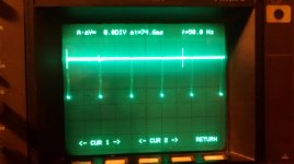
Pin 3. See picture.
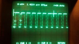
Pin 5. See picture.

I've just noticed something I hadn't before. If I power cycle the machine when the tube is good and warm, I briefly see a screen full of garbage before it clears at the bingly-beep and the screen goes clear. This suggests the screen is intentionally clear doesn't it?

The machine has two additional ROMs with hand written labels (Term ... ) in UD11 and UD12. I wondered if they are taking control instead of the BASIC so I removed them but no change.
I have re-seated the other ROMS in the hope it would make a difference but it didn't.

What should I look for next?


Thanks,
Andy.

Pet4032-J7-pin3.jpgPet4032-J7-pin5.jpg
 
Try reseating alll the socketed chips, especoally the BASIC ROM. Be careful, and make sure, if you have white sockets, that the chips seem to be actually making contact in the sockets.
 
On J7 - Pin 1 Nothing.
Pin 3. See picture.
Pin 5. See picture.

This is good. You have good horizontal and vertical timing signals from the 6545 CRT Controller. So the main board seems to be running well enough to initialize the 6545 and clear the screen. Let's check that the 50 Hz interrupt is occurring. Hold down the space key and listen for a beep about every 10 seconds. If that works, we can try to fill the video RAM with data and check the video data signal again to see if it shows more activity. If so, and if the screen is still blank, we may have a problem with the video amplifier on the video board. However if the video data signal shows no activity, we have a problem in the main board which may be easier to fix.
-Dave
 
Hi Dave_m and KC9UDX, Thanks for the input.


I have lifted and re-seated the socketed chips but to no avail.

Holding down the space bar for 10 seconds or more doesn't give a beep so I looked around a bit. Pin 4 on the 6502 (_IRQ_) is low. Pin 6 (_NMI_) is high. Surely pin 4 should be mostly high?

Looking at sheet 1 of the schematic I see _IRQ_ going off to sheet 2 (UB16 6520 pins 37 and 38), sheet 3 (UB12 6520 pins37 and 38) and UB15, 6522 pin 21.

UB16 looks to only worry about the IEEE-488 port. UB2 is connected to the keyboard. UB15 has its fingers in many pies.

I suppose any of those could be holding the _IRQ_ low. (Am I reading this right?)


[Typing and experimenting at the same time]

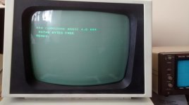
I've tried removing UB16 as I don't need IEEE at the moment and the machine has come up! BASIC V4 31nnn bytes free. The whole 9 yards :)

:)

Pet4032-StartUp.jpg

UB12 is also a 6520 and appears to look after the keyboard. I'd like to swap the two 6520s and see if the fault follows the chip or the location but UB12 is not socketed.

What do you think now chaps? Is it likely to be the 6520 or something around it?


Thanks again for the help. It's feeling quite close now.


Cheers,

Andy.
 
Last edited:
I have lifted and re-seated the socketed chips but to no avail.
I apologise, I was reading a cached copy of this page and didn't see that you did that until I posted.

I suppose any of those could be holding the _IRQ_ low. (Am I reading this right?)
Yes.

I've tried removing UB16 as I don't need IEEE at the moment and the machine has come up! BASIC V4 31nnn bytes free. The whole 9 yards :)
Congratulations! You've isolated the problem very quickly.:)

What do you think now chaps? Is it likely to be the 6520 or something around it?
Yes. Go ahead and swap 6520s, one at a time, installed one at a time, and see where the problem goes.

When I first got my 2001N, it had the same problem. In my case, it turned out to be both the 6520 and something else. My memory is bad on this but if there's a keyboard matrix decoder there, that was also bad. In your case, it could be one or the other or both.
 
What do you think now chaps? Is it likely to be the 6520 or something around it?

Andy,
Great work.

I agree with KC9, the 6520 UB16 is most likely the culprit and not any of its support chips.

Does the cursor blink, indicating the 50 Hz interrupt is working and responding to keystrokes, etc.? If so the keyboard 6520 is OK. It uses the Vertical Drive signal as an input to cause an interrupt. It is possible that you will need to replace UB16 before the rest of the PET will work properly. The Motorola 6820 and 6821 will work as replacements for the 6520 if they are easier to find.

Your keyboard will probably need cleaning to get all the keys to respond. That is not a hard job. Cleaning the rubber/carbon pads with isopropyl alcohol or a contact cleaner should do the job.
-Dave
 
Last edited:
Well done Andy.

Nice looking video synch. signals :).

The simplest problems are always the best to diagnose. A bit of probing around the obvious with a scope - power, clocks, NMI, IRQ - hello, what's going on here?

The IEEE PIA usually does go duff for some reason...

Oh well - a replacement chip and a bit of a clean around (plus checking out all of the functions) should get you a nice working PET.

Dave
 
Thank you guys.

Apart from the PIA I think the machine is fine. I'm calling that mended (mostly). I'll try to source another 6520 when I can.

I should have done this as part of the RetroChallenge. It would have been the first time I'd ever finished one ;-)

Thanks again for all of your help. I wouldn't have had a clue without you. I feel a bit wiser and better equipped for next time now.


All the best,

Andy.
 
Hello,

I just thought I'd post a follow up.

I picked up a replacement 6520 from ebay that arrived safe and well, popped it in place and the machine is as good as new.

The previous owner was an experimenter, he built a Z80 based machine in the early '80s, and I suspect that an interfacing project went a bit wrong. ;-(. however, it's all fine again now.


Cheers,

Andy.
 
Back
Top