• Please review our updated Terms and Rules here

PET 2001 chiclet... square blocks on the screen ?

simplex

Experienced Member
Joined
Mar 12, 2014
Messages
171
I've just acquired a PET 2001 with chiclet keys .

When powering on, it hums and displays nothing but these solid blocks (which do not change position or shape.)
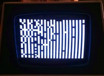
pet screen.jpg

There is nothing missing from the logic board and it came from the original owner who never modified or attempted to repair it.

Tried already : swapping RAM, swapping video ROM. This slightly altered what was on screen but did not fix it.

Doesn't get any further, datasette doesn't operate, no response from keys... I've seen the usual garbage screen before, on other PETs, but never this blocks one.
any clues?
 
Last edited:
Hm - that's an interesting display!

I suspect that (a) the processor itself is not working (hence the 'static' display on power up) and (b) there is something also wrong with the video generation logic (you should have a random collection of alphanumeric and graphics on power up - both in normal and inverse video).

If you power off and power back on again (after - say - 1 minute being off) do you get different results each time (i.e. is the video RAM initialising slightly differently each time you power on)?

What sort of a background do you have and what test equipment do you have access to? For example, can you read electronic schematics; can you solder/desolder; do you have access to a multimeter, oscilloscope and/or logic probe?

One simple thing you could do initially (if you have a multimeter that is) is to measure the AC supply voltages from the transformer and the DC supply voltages from the on-board regulators to see if they are in spec. The next simple thing might be to remove each socketed IC; clean the pins and re-insert the IC again (identifying the correct orientation before removing it). Over time, a build-up of oxide on the IC pins or socket can cause problems.

I don't expect the above to actually cure your problem - but it gives us a starting point to work from.

If you haven't found them already, the PET schematics are online here "http://www.zimmers.net/anonftp/pub/cbm/schematics/computers/pet/2001/index.html".

Dave
 
Taking a bit of a flyer - and assuming the video section specific to your make and model of PET can be found at http://www.zimmers.net/anonftp/pub/cbm/schematics/computers/pet/2001/320008-3.gif - I would say that you have a fine horizontal and vertical drive signal to the monitor (and I think I can count 40 columns of 'characters' on the screen). Also, the video drive signal is there (otherwise you would either get a black or white screen).

My guess would be that something is happening around B2 (parallel to serial converter) or A2 (ROM character generator) in the first instance. (Again - I am making an assumption about the specific schematic related to your make and model of PET - so we need to confirm this). If the character generator ROM is removable (which - from what you have said in post #1 appears to be the case) - remove the ROM and jumper the data lines from the CHARACTER GENERATOR ROM (A2=6540) to the parallel to serial shift register (B2=SN74LS165) in various patterns to see what you get on the screen. If all 8 lines are logic '0' - the screen should be blank. If all 8 lines are logic '1' - the screen should be white. Various patterns should correspond to the same 8-bit pattern being repeated for each row of each character on the screen. If this is not the case - it is most likely either A2 that is at fault (74LS165 - the parallel to serial shift register) or the signal feeding /LOAD (on pin 1).

It would help if you had an oscilloscope or logic analyser to monitor these points.

Basically, we first need to get the video circuitry working - and then we can move on to the main processor itself.

Don't forget - there are mains voltages (110V or 230V) in the case plus the EHT voltages around the monitor (which can kill) so keep this in mind when you have the case open and are investigating inside.

Dave
 
If you power off and power back on again (after - say - 1 minute being off) do you get different results each time (i.e. is the video RAM initialising slightly differently each time you power on)?

I second the desire for clarification on that: if you turn off the PET, walk away, and turn it back on in five minutes do you get *exactly* the same pattern on the display? Because if that's the case it's a fascinating failure. It *almost* looks like there's a pattern that might be related to the memory address of the characters, but it could simply be an illusion.
 
It *almost* looks like there's a pattern that might be related to the memory address of the characters.

Yes, that's it. Counter A1 (74LS93) gets clocked every horizontal scan line and its output forms the lower 3 bits of address into the ROM character generator to select the eight rows of each character. The counter is broken or it's not getting a 'Display On' Clock at pin 1. That may get you to the next step.
-Dave
 
Yes, that's it. Counter A1 (74LS93) gets clocked every horizontal scan line and its output forms the lower 3 bits of address into the ROM character generator to select the eight rows of each character. The counter is broken or it's not getting a 'Display On' Clock at pin 1. That may get you to the next step.

Hrm. (Note, what follows is me asking a stupid question for edification/education/enlightenment, not any doubt that you're onto something.) If that counter were stuck, wouldn't each character cell be the same 8 lines of a random character instead of a solid block? (Unless the particular character happened to be something that had a solid line of pixels across the row that were stuck, of course?)

(Or maybe there's something else going on that's keeping the shift register from actually being loaded with lines from the character generator or the generator is bad and just spitting out 0's or 1's? I guess if that were the case then the presence of both white and black boxes would be due to the inverter that's sitting on D7 from the RAM output, IE, we *are* seeing random characters from VRAM there, but the only "part" of them we're seeing is the state of bit 7 expressed in the form of the reverse video switch?)
 
If you pull out the character generator or pull its outputs all low or all high the 'garbage screen' looks like that only more random, I would expect.Actually based on my experience that looks much like a normal boot screen after the garbage screen clears, when there is bad display RAM (and dead character generator buffer chip).When my PET was new it would be trying to say*** COMMODORE BASIC 4.0 ***31743 BYTES FREE?SYNTAX ERRORREADY.?SYNTAX ERRORetc.It would get a handful of syntax errors(without my intervention) before just. locking up. There was a pattern of $ characters almost perfectly every other character except in the bottom half of the screen they would be more spread out.
 
Last edited:
Hopefully that makes sense because I can't format it readably. BASIC was interpreting bad screen RAM as operator input. That plus a pattern of $s and a sprinkling of random characters looked very similar to that. Except my bit 7 was stuck on so everything was imverse.
 
Hrm. (Note, what follows is me asking a stupid question for edification/education/enlightenment, not any doubt that you're onto something.) If that counter were stuck, wouldn't each character cell be the same 8 lines of a random character instead of a solid block?

I think you are right. I thought the first row of pixels in a character was always blank for spacing but that may not be true.

(Or maybe there's something else going on that's keeping the shift register from actually being loaded with lines from the character generator

No, but if the load was working properly loading random RAM data, but the shift register clock was not working or clock input was missing, that might cause these patterns.


or the generator is bad and just spitting out 0's or 1's?

It is hard to believe a ROM could fail like that with one address putting out all ones and the next all zeros.
 
It wouldn't have to. If it /always/ outputs all 0s the display would probably look like that. The same is true if the ROM /always/ outputs all 1s.

In fact it does appear that is what's happening. Or it could be the shift register. Bit 7 (inverse) is independant of the ROM and shift register output. But it is always the same for a given character block, just like what we're seeing.
 
As always though that is only part of the story. Either display RAM is being cleared incorrectly or our freind Bit 7 is being mixed with display ram A0 somehow.
 
It wouldn't have to. If it /always/ outputs all 0s the display would probably look like that. The same is true if the ROM /always/ outputs all 1s.
I see what you are saying. The ROM outputs are stuck at all one or all zero and the reverse video bit from the RAM causes the patterns. That is possible.
 
As always though that is only part of the story. Either display RAM is being cleared incorrectly or our freind Bit 7 is being mixed with display ram A0 somehow.
It is possible that the processor is also not running well enough to clear video RAM but that would imply a second problem in this PET. Commodores never do that, right ;)
 
I see what you are saying. The ROM outputs are stuck at all one or all zero and the reverse video bit from the RAM causes the patterns. That is possible.

Another possibility is for whatever reason the shift register is just spitting out zeros or ones (Or "effectively" spitting out zeros or ones, that is, because its output is just stuck high or low?), again leaving it completely up to the inverter whether a character position is black or white.

Still would like to hear from the OP if the pattern of the white and black blocks is the same between power cycles; there's just enough ambiguity in the statement of them "not moving" to leave that unsettled. I vaguely remember that when I was using the debugger in my PET to look at a toasted ROM chip that the dead component produced a *mostly* repeating pattern when it was read by the system; maybe the pattern of blocks is indicative of a *really* dead VRAM IC? (IE, we have both a failure in the character/pixel generation portion *AND* dead VRAM?)

One thing that could be useful to know is which exact model of 2001 this is, IE, is it the one that uses 2114s for RAM, or does it have that harder-to-find MOS memory?

It is possible that the processor is also not running well enough to clear video RAM but that would imply a second problem in this PET. Commodores never do that, right ;)

Yep, it's never more than one, never ever. ;)
 
Hi, thanks for all the replies, I have a lot to digest!

To answer the questions :

).

If you power off and power back on again (after - say - 1 minute being off) do you get different results each time (i.e. is the video RAM initialising slightly differently each time you power on)?

I thought initially it was identical but after taking a couple of pictures, I can see some variance in the pattern - see attached pics.

What sort of a background do you have and what test equipment do you have access to? For example, can you read electronic schematics; can you solder/desolder; do you have access to a multimeter, oscilloscope and/or logic probe?

I'm rather a novice but am OK at following instructions, My soldering has been acceptable enough to build kits like XTIDE, and I can desolder components without destroying boards. I have a multimeter, can check voltages etc, but my overall experience is pretty low and I have no scope or probe :(

One simple thing you could do initially (if you have a multimeter that is) is to measure the AC supply voltages from the transformer and the DC supply voltages from the on-board regulators to see if they are in spec. The next simple thing might be to remove each socketed IC; clean the pins and re-insert the IC again (identifying the correct orientation before removing it). Over time, a build-up of oxide on the IC pins or socket can cause problems.

I don't expect the above to actually cure your problem - but it gives us a starting point to work from.

Thanks I'll give that a shot!

If you haven't found them already, the PET schematics are online here "http://www.zimmers.net/anonftp/pub/cbm/schematics/computers/pet/2001/index.html".

Dave

Thanks :) I do find schematics useful to refer to even if when I don't understand all the symbols etc.

Some other information about the system :

It's a 320132 logic board, with 2114 RAM and 6450 ROMs.

Pictures taken about 5 minutes apart after powering off:

petscreen3.jpgpetscreen2.jpg

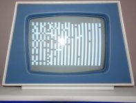
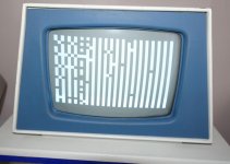
P.S. on powering off, a very bright white spot appears in the centre, like an old TV but much brighter - I hope that's normal?
 
That's good - so the video fault isn't a 'hard' one - the video contents do change (implying 'something' is being read from the video RAM and displayed - albeit not correctly!)

Bright spots in the middle of the screen aren't normal - but let's not worry about that one for now (we have enough to keep us busy for a while trying to get the video and CPU to run).

Dave
 
If removing the character rom on my 2001 I get just filled chars and empty chars - but a bit more random. Has it been checked to be OK? What about the video ram, tried swapping it to see if startup gives a more random pattern?
 
If removing the character rom on my 2001 I get just filled chars and empty chars - but a bit more random. Has it been checked to be OK?
That implies the video shift register is working OK, but doesn't prove character ROM is necessarily perfect.

What about the video ram, tried swapping it to see if startup gives a more random pattern?

Yes power-on random pattern should change to new pattern. Removing both video RAMs should give a checkerboard pattern.
 
Back
Top