• Please review our updated Terms and Rules here

PDP 11/45, Part 5

Marty,

The computers that I work on have to run at 131F for a minimum of 96 hours at full load with no faults. One of the systems needs 2kW just for the fans.

We chased microcode problems like this for weeks on the PDP-9. The microcode board was both temperature and vibration sensitive. We finally connected a logic analyzer to the microcode signals so we could see the address and the ROM (MC09 ROP memory on a PDP-9) outputs. We found some bad microcode bits that changed the next microcode address and made the machine do some really unusual things.
 
Hi All;

M-Thompson, Thank You for Your clarification..

"" The computers that I work on have to run at 131F for a minimum of 96 hours at full load with no faults. One of the systems needs 2kW just for the fans. ""

That was most likely about what We were doing, It's just been so many Years ago, that I couldn't remember the Details..

"" We chased microcode problems like this for weeks on the PDP-9. The microcode board was both temperature and vibration sensitive. We finally connected a logic analyzer to the microcode signals so we could see the address and the ROM (MC09 ROP memory on a PDP-9) outputs. We found some bad microcode bits that changed the next microcode address and made the machine do some really unusual things. ""
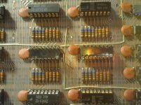
I may be forced to do the same, I have just noticed that when it's running I can get it to do the failure, but single Stepping , it shows the correct codes now..
I have replaced a number of things, the UA MicroDriver Inverters and the Microcode Address Drivers for the Proms..

"" We found some bad microcode bits that changed the next microcode address and made the machine do some really unusual things. ""

Been there it's done that..

THANK YOU Marty
 
When I was working on the diagnostics for the PDP-11/60 at DEC, we were seeing failures of some of the first off machines in the thermal chambers. They would cycle from 0'C to 50'C and back again, stopping at each extreme for an hour or so. At this point I don't recall the exact failure that was being seen, but I do remember going into the thermal chamber (an 8x8x8 box) and having to alternately either wear a coat (provided locally) or use a towel to sop up the sweat, depending.

Don
 
Last edited:
Hi All;

AK6DN, Thank You for that bit of DEC History..

We didn't do the cold thing.. But, I do remember reading about DEC's Hot and Cold Rooms and seeing some pictures in the DEC book by Bell..

I think Out Hot Room was about a 6' by 8' or 10 ' ..

Dave, I am picking up on some things I missed in Your post #140, that I had missed by just reading of it, while copying it, after I do #140, I need to do posts #93, #106 and #159 ..
I have finished copying post #140 and I am working on Post #93, which is loaded with all kind's of useful information, that I did not see before..
Post #93 is copied and now on to post #106.. The same as above, more of what I did not see.. I have finished copying post #106 and I am doing Post #108 now.. I am now on to Post #159.. Post #159 has been copied, and I went to Radio shack and got some tips..

"" If you remember back to the '8' we broke the debugging down into quite small chunks - with zero assumptions. We managed this because the chips were socketed and you had no problem pulling one out and replacing it with a little test board - or re-wrapping the wiring for a test. We don't have that luxury with the 11/45 so we have to try and 'break the loop' somehow. This is the purpose of the maintenance card (we can single step the microcode - clock edge by clock edge if necessary) to deduce where the error actually is. ""

This is sort of what I plan on doing a little later, I will need to stop by Radio Shack and Hopefully pick up some tips for my Desoldering tool and for my soldering iron..
And then I can take out the rest of the 74174's which are the Data Word latches, and bring both the Data and the Addresses out to a BreadBoard like I did with the '8'..

I have done the replacing of the 74S174's, and Now it doesn't work on first power up, I will do some inspecting and some cleaning and then some Breadboard time..
I found the Problem, I had it in Push Button single step clock mode, and not in normal mode..

THANK YOU Marty
 
Last edited:
Hi All;

I have put sockets in all of the ROM positions in both the M8103 and the M8123, So the Proms can be switched to the M8123, and that Board can then be made to look like an M8103..
One other thing I noticed was that the printed Circuit Board was Scorched under the Proms..
There might be some wiring modifications, that might have to be done to make signals from the M8123 look exactly like the signals of the M8103..
But, If I can make this work, then either it will fix the problem or it will not fix the problem..
If it doesn't fix the problem then it is either a problem with the Proms themselves or it is on another Board..

Also these proms can Now be read and a master bin file made for them..

THANK YOU Marty
 
Last edited:
Hi All;

I have Just Found two of the Proms have a Burned spots on the Back of the Proms..

Here is a Picture, Ignore the Orange light, that is the Flash passing through my finger, while covering the flash up..

001.jpg

The IC on the left actually has some of the Plastic missing..

This is Now sinking into my realization, that this may be what is making my machine into a Non-working 11/45..

I need to find/make a way to read the Proms, and Verify what is Good and IF any of it is No Good..

I think If I pull some of the 7404's that I socketed and put it into my Tester and add a few bells and whistles I can Read the Proms and compare them to the listing..

Also, I am thinking, that I will bring out with two cables, the two (possible bad) Proms and make a circuit with an Eeprom (which I have) and program it and see if I can make the 11/45 work any better..

I can see that I am going to have to make a 64 bit by 256 bit chart in one of my NoteBook's, so I can use that to compare what I see to what is supposed to be there in the original listing..

Well, I have the first 14 Instructions copied down into my NoteBook, so now I can put the Board into my Tester and see 'how' things compare..

THANK YOU Marty
 
Last edited:
Hi All;

I have started to fill in the next few pages of 14 Instructions each, so that I am down to address '067 octal, I will do one more page, so that I can get to the next page with address '070..
Ok, the '100's are paged out. Next is the '200's
It looks like I will need to start a new NoteBook for the '300's, so most likely, I will just start out with a new all Blank NoteBook for the MicroCode Listing, as only the first 14 Instructions are the only ones fully done, it won't be too bad to recopy things out..
I'LL see if I have another NoteBook to do this in or do I need to get another one from the store..
Yes, It didn't fit, so I am starting another NoteBook.. I will need to pick some more NoteBook's next time I am at the Store..
I have done a basic copy into a new NoteBook, along with the Explanations for these terms..
Ok, I have the first 14 Instructions fully copied into the new NoteBook, so I am about where I was before in the other NoteBook..

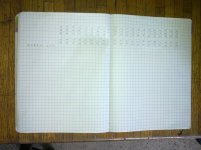
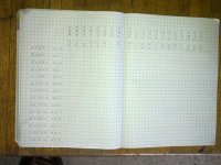
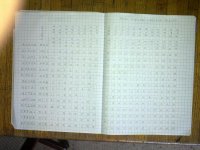
Here is some photo's of what progress it takes to get a page done..

004.jpg 003.jpg


002.jpg 001.jpg

I still have to fill in the individual bits for each of these sections, so it is slow going.. I was busy Yesterday with other things, so I didn't get anything done, on the 11/45..

I have found a way to help speed things up, but eye strain is what is slowing me down at the present..

I just tried to use the KM11 by Shiresoft, and I found out that at present I cannot use it..
It uses the +8 volt line for the Led Drivers and the Led's and I don't have a +8 Volt supply..
I can Cut the Trace and wire it to the +5 volt line, I just haven't decided whether I want to or Not..
My home made units use the +5 volt supplies..

THANK YOU Marty
 
Last edited:
Marty,

If you haven't wired up the +8V supply - it should be 'floating' so there is no Need to cut the trace. Just wire the +8V to +5V and you should be good to go!

Dave
 
Instead of a notebook for the microde, how about using Excel?

I bet that you could write a macro to execute the microcode in the spreadsheet.
 
Hi All;

Dave are You back from Your too short Vacation ??

It is a matter of not knowing where that +8 lines goes to in other parts of the Machine, that has held me up from doing that..
I figured I had blown up enough already, Thank You for Your Insight though..

M-Thompson, Thank You for Your suggestions..
"" Instead of a notebook for the microde, how about using Excel? ""
I don't have Excel, nor do I know how to use it..

"" I bet that you could write a macro to execute the microcode in the spreadsheet. ""
Maybe YOU Could, But I wouldn't even know How nor have a clue as to where to start to do that..

And that much time staring at the Computer screen, would give me headaches and eye strain 100 times worse than when I do it on paper..

Micro-Rom listings '000 thru '077 are all done.. Next is '100 thru '177..

THANK YOU Marty
 
Last edited:
Hi All;

Thank You, M-Thompson, for the suggestion, If I ever get that far I will look forward to Running that file/program..

As, You might already know, First, of course I need a running 11/45,
Secondly, an SMD Disk Drive that will work with my Disk Controller,
and thirdly RSX-11M PLUS..

That's still a Tall Order..
Thanks for giving me some hope..

I got Addresses '100 thru '177 of the Micro-Rom words copied.. Next is the '200's..
The '200's are done, next is the '300's..
The '300's are Done, so I have the whole thing copied into a NoteBook..
Now, to bring out the two Proms, which I can do, and put them to Drivers and Led's and see what happens, when things warm up..
I suspect, since one of the Proms is for the 'AMX and 'BMX, that this is where the Trouble resides, the other prom is for the lower four Address lines to the Proms, which can mess things up as well..

THANK YOU Marty
 
Last edited:
Instead of a notebook for the microde, how about using Excel?

I bet that you could write a macro to execute the microcode in the spreadsheet.

In hand (along with the pinouts for each of the backplane connectors)... It may take a while though.

I am entering the microcode (and slot pinouts) into EXCEL from the paper schematics I have that came with my machine - so they are a little more legible than the scans on BITSAVERS (this should result in potentially fewer transcription errors - although the EXCEL sheets will still need someone to verify them for correctness).

I plan to regenerate the 64-bit HEX for the ROMs (e.g. 0xDEADBEEFCAFEBABE) from the microcode field layout - so the 4 bit ROMS can be checked using a conventional EPROM programmer.

I will also add the 'option card' microcode extensions as well.

Just before I do (and waste my time...) - I assume this information is not available electronically elsewhere is it?

I will also generate an import file for LOGISIM from the microcode. I have already started a new LOGISIM project called PDP-1145 - no prizes for guessing what this is!

Dave
 
>> Dave are You back from Your too short Vacation ??
>>
>> It is a matter of not knowing where that +8 lines goes to in other parts of the Machine, that has held me up from doing that..
>> I figured I had blown up enough already, Thank You for Your Insight though..

Just - got back last night.

From looking at the schematics (in particular 1145_System_Engineering_Drawings_Jun74 page 127 of 192) it shows +8V from pin B1 of slot 1 row F being connected to J2-8 via wire-wrap pin SP1. P2-8 is then wired to the upper H742 on P14-1 (which is the +8V output).

The physical backplane PCB (page 115 of 192) shows a small copper trace from pin B1 of slot 1 row F to pin B1 of slot 1 row E (powering both the CPU and FPP maintenance cards with +8V ).

You should find a wire-wrap from the E/F row connectors on slot 1 to the +8V power supply arriving on J2-8. You should then be able to trace this wire to wherever it goes in your wiring loom. Visual inspection should identify that it shouldn't go anywhere else - but it would be worth a few checks with a magnifying glass, bright light and a multimeter though - just as a sanity check.

I am not going to do much this week - whilst I recover from the vacation!

Dave
 
Hi All;

Dave, Thank You for the Tremendous amount of work that You are and are going to put into Documentation..

On the side note, I will check out the +8 situation..

"" I am not going to do much this week - whilst I recover from the vacation! ""

OK, I hope that all went well and You are OK..

From Your other posting..

"" In hand (along with the pinouts for each of the backplane connectors)... It may take a while though.

I am entering the microcode (and slot pinouts) into EXCEL from the paper schematics I have that came with my machine - so they are a little more legible than the scans on BITSAVERS (this should result in potentially fewer transcription errors - although the EXCEL sheets will still need someone to verify them for correctness). ""

As, You know I have started doing this in my NoteBooks both a ROM listing and a cross reference pin out and a eventually a backplane wiring connection chart..
If any of what I have would be of any help, I would be more than happy to scan it, and get it to You somehow..

"' although the EXCEL sheets will still need someone to verify them for correctness). ""

I can verify them against what I have, if You need someone to do that.. Both from my NoteBooks and with my tester..

"" I plan to regenerate the 64-bit HEX for the ROMs (e.g. 0xDEADBEEFCAFEBABE) from the microcode field layout - so the 4 bit ROMS can be checked using a conventional EPROM programmer. ""

I had mentioned to Fritzm, about starting a Prom File database for all of the proms in the 11/45, so that if anyone need to use or make a new prom the file would be in the Database, like what Fritzm did with his GRA Prom, that information would be there for anyone to use..

"" I will also add the 'option card' microcode extensions as well. ""

I have never seen nor heard of those, where and which slot do they plug into ?? Is there a Schematic for these ??
And a listing for the Additional Proms ??
I am getting more interested in the who does what and how of the Micro-code and how each fragment makes something happen..
On a side note, Once I can figure it out, How to use it, my Step Engineering System, is a writable memory that to the 11/45 looks like a Prom, so it's changeable from the Step System side, but Not from the 11/45 side.. So with it, If I feel like it, I can explore all kinds of possibilities..

"" Just before I do (and waste my time...) - I assume this information is not available electronically elsewhere is it? ""

Not to my knowledge..

I will also generate an import file for LOGISIM from the microcode. I have already started a new LOGISIM project called PDP-1145 - no prizes for guessing what this is! ""

YES, !!!!!!!!!!!!!!!!!!!!!!!!!!!!

THANK YOU Marty
 
Last edited:
Hi All,

I'll be digging in on the FPU on my 11/45 this weekend. I've noticed that the source listings for the diagnostics CFPA-CFPL are not included in the diagnostics database over at retrocmp, nor could I find them on bitsavers. Does anybody know where I might obtain these?

cheers,
--FritzM.

P.S. Dave: I'd be happy to lend an extra pair of eyes to verify the spreadsheets you are developing.
 
Marty:

>> I am not going to do much this week - whilst I recover from the vacation!

When we go on a European Holiday (as we did this year to Hamburg/Germany) we tend to do a lot of walking - hence the need to recover!

>> I will also add the 'option card' microcode extensions as well.

These cards are nothing more than the FP11-B (which has its own microcode ROMs and state machine) and the KT11-C (which 'extends' the CPU microcode ROMs).

Marty/Fritz:

I have just entered all of the microcode for the 11/45 CPU into EXCEL and 'consistency checked' it with some EXCEL VBA. The consistency check found a few issues (which I noted and resolved). Some of them were my own typos though!

I am now in the process of 'fighting' EXCEL VBA to 'play nicely' with 64-bit unsigned integers. Unfortunately, I am loosing the battle and may have to 'change tack' slightly tomorrow. I am close though in recreating what should be in the microcode ROMs (in HEX format). I still have to check the microcode field values I have entered from the BITSAVERS listing against the schematic ROM listings that came with my machine. This will be a manual job of course...

Let me check the stuff out to my satisfaction first and I will ZIP you both up a copy shortly...

Dave
 
Hi All;

I extended the two Proms out to my BreadBoard.. And I put them to Led's, so I could see what the Proms are showing..
Yet, the Proms, according to Leds are Not showing the correct Data, (yet, Addrs Load, Examine and Deposit all work)..
I was Wrong on my assessment I had swapped them and the Prom for the Prom address data, I thought was the AMX, BMX data and
the AMX, BMX data I thought was the Rom address data, so actually, for what I looked at they were correct..
Of course they had not warmed up yet, so I did not see if that made any difference or not..
So I am going to make a change of Plans for next week,
I will use an EEprom, in place of the Proms and see what it shows, on the Data Led's..
Ok, I've wired in the EEprom, but it still needs to be Programmed..
Or another possibility is to make a Prom Reader, using an FPGA Board, like a Spartan 3.. What a nightmare that would be, programming wise..

THANK YOU Marty
 
Last edited:
Hi Marty,

A ROM scanner for an FPGA board is not too bad -- I put one together on a Digilent Nexus board to scan out the character generator ROM on my VT52. You can find the Verilog code for it at https://github.com/fritzm/vt52/blob/master/scanner/chargen-dump.sv if that is helpful. Beyond this little bit of code, you'd just need a pin configuration file for your specific FPGA board and tools. I also had to hook up some level-converter chips between the 3.3V FPGA board and the 5V ROM.

My Nexus board runs at 100Mhz. If your board has a different clock frequency, the divider count would also need to be adjusted for the 9600 baud bit clock.

cheers,
--FritzM.
 
Last edited:
Hi All;

Thank You, Fritzm for the suggestion..
I'LL look to see if I have a Nexus Board or not, otherwise I know I have a Spartan Board..
And I'LL give it a try, But, I may have alot of to You silly Questions, about what and where of the coding..
I'LL look at Your Code, and what I have, also what Level converter chips did You use ??
FritzM, I have a Nexys 2 and a Spartan 3E FPGA board(s)..

On a side note, Dave when You get Your Micro-code to where You think it needs to be, and then sent out to FritzM, and He thinks it's OK..
Then I can send Him a few Hopefully Blank Proms, which He can Program, (which He has already said He is willing to do)..
Which is another reason for me to get a Prom reading Digilent board going, to verify that the Proms that I have are Blank..

THANK YOU Marty
 
Last edited:
Back
Top