• Please review our updated Terms and Rules here

PDP 11/45, Part 5

I was wondering when we would get a new thread...

Just got back from Church. A few of us meet once a month to fly model helicopters inside the Church hall. We have now extended this to model boats and cars - although we can't float a model boat inside there without getting told off - we have to wait for the British weather to smile on us for that one :)!

Anyhow - I took my disassembled H742 down with me (not a model the real one) and almost got it reassembled once again. I will get our lab technician to put some 1/4" spade connectors on my newly acquired black toughened rubber mains cable and I should be able to fire it up (minus the voltage regulators) and check that everything is safe and that I have a working transformer and fans.

Repeat once again for the other h742...

Dave
 
Hi All;

Dave, ""I was wondering when we would get a new thread... ""

I was hoping that #4 would be the last one, when I had it working and Passing all of the Tests..

Then, after it went South, I needed a good place to Interrupt things and make a smooth transition..

"" Anyhow - I took my disassembled H742 down with me (not a model the real one) and almost got it reassembled once again. I will get our lab technician to put some 1/4" spade connectors on my newly acquired black toughened rubber mains cable and I should be able to fire it up (minus the voltage regulators) and check that everything is safe and that I have a working transformer and fans.

Repeat once again for the other h742... ""

I can't wait to hear that You have or are having SUCCESS !!

Three twelfths of the Tester is wired..

THANK YOU Marty
 
Last edited:
Hi Dave,

I recently refurbished a pair of H742s for my own project. The trickiest bit was making sure the small cooling fan over the control board had good mechanical clearance of all the leads in there on reassembly, so it wouldn't jam up and leave the regulator to cook.

I also found the vintage neon indicators were worn out and flickery. I got replacements that were very close to the originals at newark: http://www.newark.com/chicago-minia...-634r/lamp-indicator-neon-red-125v/dp/02F3677

cheers,
--FritzM.
 
Hi All;

Fritzm, Thank You for the Information and for the Link..

I have another section all wired up, which makes about 1 / 3 of it done..
I still have to test it with power and with my pulser, to make sure I have it all wired correctly..
It seems like it takes about a Day to wire up a section..

002.jpg

THANK YOU Marty
 
Last edited:
Hi FritzM,

I have been following your blog - excellent work. I must get around to creating a blog of my own - I am taking copious notes and photographs - but it is yet another thing to do...

Thanks for the link to the neon lamps. The only things that aren't working too well on the 861 Power Control Unit are the neons. They work enough for now - but I would like to find a replacement in the longer term.

I have found a source for my missing front panel knob - but I haven't received a response to my e-mail yet. Perhaps selling one or two off to a large company is not cost effective. I will try the tack of 'why don't you send me a free sample' and see if that works...

Thanks for the info.

Dave
 
Hi All;

I guess, I need to ask what is the difference between what we do here and a blog, other than it is one side, that is only the author can add or contribute to it, where as here everyone can contribute ??

"" I have found a source for my missing front panel knob "" I think You may have noticed I use chicken-head knobs, I have blue ones at the present, but I had Orange ones in the past and yet have purple ones to go.. I am still evaluating which color I like best..
So, Dave if You get an extra pair let me know what they look like, compared to what I have..

On to the next section on the MACT Tester, when that get all wired up, it will be half way done..
And then I will need to decide whether to borrow more 20 pin ID Wrap Stickers, or wait for the ones I ordered to come in before I continue on with the project.. But, for this section I am OK..

THANK YOU Marty
 
Last edited:
Hi Dave,

For the 861 neons, I found these replacements: http://www.digikey.com/product-search/en?keywords=1050A4-ND.

Also, you'll probably find at least some of the indicator bulbs in your DC regulators are shot when you get to those. For the the H744 +5V regulators, I subbed http://www.mouser.com/ProductDetail/VCC/7381/?qs=sGAEpiMZZMtj1PWpWL2%2bvIah2%2bQ2O2a3Uixk2hsfQqM=. For the H745 -15V regulators, I found https://www.bulbworks.com/light-bulbs/OL-6003BP.

Those 15V bulbs are out of production, and are kinda pricey from that supplier... This is a popular bulb with the PDP-8 crowd, too, so they may get harder and harder to find as stocks diminish.

I'll start putting part numbers/sources in my blog entries in case others find it helpful.

Marty, re. blog vs. forum: I view the blog kinda like my own personal notebook, where I can ramble about anything I like and nobody has to listen :) Though lately its been almost all PDP-11/45 over there... I see the forum here as chatting with knowledgeable friends at the pub -- it's a little noisier, but a lot more social :)

cheers,
--FritzM.
 
Hi All;

Fritzm, Thanks for Your Helpful suggestions..
And the difference between a Blog and our postings in this forum..

Years ago, when I needed light for my Data General Nova's I would use a 16 to 18 volt bulb, for their front panel, which at that time I could get at the Local Hardware store..
And they would work just fine.. And might be better in Price.. Just an Idea..

And since I was missing so many bulbs on my PDP 11/45, I went to Led's as most of You may know, I had to change the input voltage with a dropping Resistor though..

THANK YOU Marty
 
Hi Dave,
For the H745 -15V regulators, I found https://www.bulbworks.com/light-bulbs/OL-6003BP.

Those 15V bulbs are out of production, and are kinda pricey from that supplier... This is a popular bulb with the PDP-8 crowd, too, so they may get harder and harder to find as stocks diminish.

http://www.so-much-stuff.com/pdp8/repair/bulbs.php

Mouser has CM7370 equivalents as part numbers 560-7370 and 560-8099SBP. the latter being a little more expensive, but lower power and longer lasting.

Vince
 
Hi All;

I got the MACT Tester half way wired..
Three more Sections to go.. Tomorrow I should be getting the rest of the Parts I need..
Those Parts should come in today.. A day late..
I almost got the fourth section all wired up, 18 more wires to finish..

And then I can start on the fifth section..

THANK YOU Marty
 
Last edited:
Hi All;

I have about 45 wires to go and the fifth section will be done..

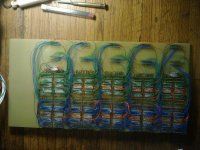
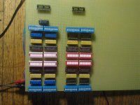
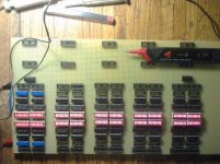
Five sections are basically done.. The reason I say basically is that I already have planned on some needed additions, But, first I will get the unit to work before I make any changes.. One I will be adding some 555 timers and extra sockets to make it so I can wire up those 555's to any signal pin..

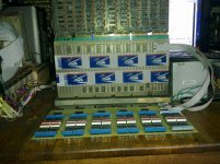
Here are some pictures of the progress so far..
001.jpg 002.jpg


Section six is being wired up..

OK, I'm down to my last 18 wires.. Then I know that from last night, I have four signals to fix and not counting if I find any more on what I have wired today..
But, it's getting close..
It's All wired and Tested now to wire the Backplane and see that I have that all wired correctly to put power and ground in the right places on the Backplane..

I have the MACT Tester plugged into the middle two rows, and it is showing that FJ2 is grounded, and so I am looking for the reason why..
I looked in BitSavers and that pin IS Grounded, I will try to unground it next week, I have scraped away the ground on FJ2 on another Row, so it will take more effort by me..

I got about 1 / 3 of the middle two rows wired together of the Backplane..
The module is a DD11-CK..


THANK YOU Marty
 
Last edited:
Hi All;

I got about 1 / 2 of the middle two rows of the backplane wired up..
It still takes awhile to wire up each section..
So progress is slow, but not as slow as wiring up the whole board, that I just got through with wiring..
I have just got a call from a friend, so I will be gone most of the day..
So, no more progress today..

THANK YOU Marty
 
Hi All;

I got half way wired up on the last three Sections of the Backplane, which makes me about 75 % done on it..

OK, it is All wired up on the Backplane, next to try it out, and see what I get on all of the Signals from most of the Pins..

No, more Ground on the pin that was Grounded,

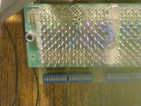
001.jpg

So, I can now, Put in a Test board and see if I get the results that I expected on it, I will try one of my Bad DATA PATHS Boards'..

Yes, it allows some lines to be pulled Low.. And nothing Bad happens.. Next to test that an IC, both input and it's output work as expected..
I will need to get out the Schematic for this Test..

OK, so I put the Memory Management Board in for the Picture..

002.jpg

I know that the cables are toooo Long, I need to measure and see about getting shorter ones.. Shorter ones are coming..

I will be going away for a day or two in about two hours.. So, I won't get much done..

THANK YOU Marty
 
Last edited:
Hi All;

I am back from my Camping trip, and at present I am worn out from my Hiking today..

I got my cables changed out to the shorter ones..

I may have found a bad Part in the Memory management Board.. I am replacing it with a socket and then, putting in another part..
Hopefully that will either Help it or fix it..
I have Replaced that IC and on the MACT Tester they do what they should be doing..
So, I can Put Both of the Memory Management Boards in place and see if they Respond any better..
At this point I can't say that the Board has been fixed, at least not until I can put it in the 11/45 and see the results..

THANK YOU Marty
 
Last edited:
Hi All;

That Fixed that Problem, BUT, there is still Other problems, at least with the lower bits..

So, I can Now chase where that problem is, One possibility is that what is turning on the 74153's for the Lower Bits is not working..

I will Use the Tester to confirm or disaffirm my Theory..

I got slightly side tracked, I found a short on two sets of lines that I had to un-short and it took awhile to get that accomplished..

I also found a wiring mistake on all of the sections, It's a simple wiring change on half of the signal lines, but, it will take awhile to get it done on all of the sections..

I will first do one section and make sure I have it correct, before proceeding any further.. This is all part of making sure things are the way I like them..
Which is why I do wire-wrapping.. OK, One section is done and checked.. Four Sections are done, two more to go.. All Sections Done..

I will do some further Testing on Monday, and make sure that everything is OK..

001.jpg

In the picture the Sockets on the right are wired correctly and the sockets on the left are Not wired correctly..

THANK YOU Marty
 
Last edited:
Yes, it allows some lines to be pulled Low.. And nothing Bad happens.. Next to test that an IC, both input and it's output work as expected..
I will need to get out the Schematic for this Test..

OK, so I put the Memory Management Board in for the Picture..

View attachment 32295

THANK YOU Marty

Would you mind explaining this setup, Marty? I can't quite reverse-engineer what's going on from the photo. But it sure looks "busy" :->.

I've guess-timated what you are doing in your WW-board, but I'm not following the hook-up above the ribbon cables in the photo.

(And how does the earlier photo of the SU WW-strapping relate to this ... if at all?)
 
Hi All;

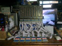
PBirkel, Thank You for Your Questions.. Here are some Photo's to help explain the Set-up..

001.jpg 002.jpg


003.jpg 004.jpg


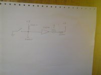
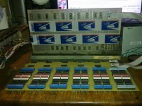
The first Picture is the Basic Schematic, The others are the same set-up as before, but with only two shorter cables for clarity..
In the Schematic I've drawn a bulb for the Led, and I have used 74LS540's to drive the Led's, but an 74LS04 or something similar could be used..
The Board being tested is raised above the cabled board, so that I can get to all of the IC's to be able to test and inject a signal on a particular IC or gate connection.. I choose the 2.2K Pull-up Resistor because that was what I had, and it seemed to Work OK, I suspect anything between 1K and 2.2K would work fine..
I could have used wire-wrap to the Pins on the Bottom of the DEC DD-11CK MotherBoard, but I found from Previous Experience that doing it that way, I used, way too much wire-wrap wire..

"" (And how does the earlier photo of the SU WW-strapping relate to this ... if at all?) ""
I don't know what an SU is and what You are referring to "" SU WW-strapping "" here ??

Does this Help ??

THANK YOU Marty
 
Last edited:
Hi All;

PBirkel, Thank You for Your Questions.. Here are some Photo's to help explain the Set-up..

...

"" (And how does the earlier photo of the SU WW-strapping relate to this ... if at all?) ""
I don't know what an SU is and what You are referring to "" SU WW-strapping "" here ??

Does this Help ??

THANK YOU Marty

Thank you Marty.

Q#1: What is the relationship between the board in pic#3 and the extender in pic #2? It appears "none". If so then what is the purposes of cabling your tester-PCB to the board in pic #3?

Q#2: In the immediately preceding post your Pic#1 showed the WW-post side of a DEC System Unit (SU) with extra wire wraps. To what end?

Thanks for elaborating.
 
Hi All;

PBirkel, Thanks for the questions..

"" Q#1: What is the relationship between the board in pic#3 and the extender in pic #2? It appears "none". If so then what is the purposes of cabling your tester-PCB to the board in pic #3? ""

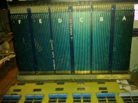
The Extender Board in Picture #3 is just to show the DEC Pinout naming like AA1, Just so You could see the relationship between Light/switch and where that would be on the Board being Tested..
The cables are to connect the Tester to the DEC Backplane so that any Board can be Plugged into the Backplane and the Tester can show the status of any Signal Line..

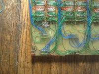
"" Q#2: In the immediately preceding post your Pic#1 showed the WW-post side of a DEC System Unit (SU) with extra wire wraps. To what end? ""

That is what connects the Board being Tested with the LED / Switch setup, and is connected to the Power Supply that provided the Power and Ground for Both the Board being Tested and the Tester..
It also ties both slots together, so
Slot #1 origionally UniBus, is not used..
Slot #2 is used to hold either the cable board or a board that is being tested..
Slot #3 is used to hold either the cable board or a board that is being tested..
Slot #4 origionally UniBus, is not used..

I hope that this helps..

I have checked and fixed lines that Were shorted and so I am Ready to Start checking the Memory Management Board Again..
Many of these were on purpose, since in it's former life it was a MUD slot..


THANK YOU Marty
 
Last edited:
Back
Top