• Please review our updated Terms and Rules here

TV Typewriter replica project back on track

One thing that will help (we really need a section on tools and techniques) is a lead-forming tool:

4PCS-Axial-Diode-1-4-to-3W-Resistors-Capacitors-font-b-lead-b-font-font-b.jpg


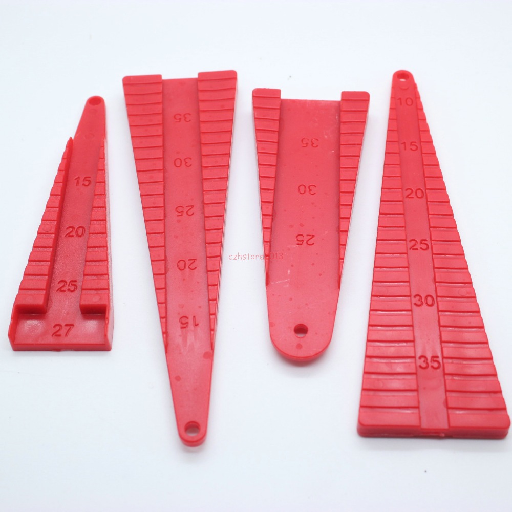
Basically, you drop the resistor so that the body fits in the center groove at the appropriate lead length indicator and bend the leads straight down. Works a treat and looks like a million bucks.

Most jumper wires that I've seen are tinned bare copper bus wire, which can also be purchased. No need to nick insulated wire stripping it:

41-J-yV5AUL._AC_UL130_.jpg
 
That is awesome! Thanks Chuck -- I will definitely grab some of those. And the bus wire.

I ended up recycling the clipped leads from the diodes/resistors to do the shorter jumpers for now, and used actual jumper wire for the two longer ones.

Any advice before I try plugging this sucker in? I've looked it over 50 times for shorts... really want to see what happens.. but don't know if power and a logic probe will be enough to make it do something.
 
Ah, white-knuckle time...

First, test the power supply and make sure it's providing the right outputs. With no load, the voltages will read high, but they'll be in the ballpark. Since this is a linear supply, you can power it off a variac and slowly crank the power up to avoid any fireworks.

Before you hook the boards together, check the continuity between each power supply rail and ground. Clearly, there should be some resistance showing, but nothing in the 0->10 ohm range, which indicates a short of some kind. Visually inspect the boards to ensure that you didn't reverse any components by mistake (capacitors, ICs, diodes). Then apply power to a single board--use the variac if you want.

If there are oscillators on the board, they should be oscillating (use a logic probe). Nothing should be overly hot or smoking.

Add other boards in, one at a time. Start with the memory board, then the serial I/O board, etc. You can smoke-test the keyboard all by itself--it should generate the appropriate codes (logic probe time) and key-pressed strobe.

You get the idea--work slowly and carefully. If you run across something that doesn't make sense, stop and try to figure out why--don't just keep plugging stuff together until you know the reason.

Good luck.
 
Sorry!! I should have been clearer.. but thanks for this.. I *will* use it eventually. Right now the only complete piece I have here is this encoder.. I was wondering if I could use one of my existing power supplies, connect it up.. and then use a logic probe to see where things are at? I'm assuming to test without the keyboard you'd need to short connections in a way that simulates a keypress on the matrix?

I'm further guessing that power comes in on the smaller edge connector.. I believe that's the one that would ultimately connect to the TVT mainframe, which would be supplying the power..
 
Hmmmmm.. my homemade CT1024 has a terminal strip with a 10V lead on it. I wonder how risky it'd be to connect this ASCII encoder to it. The wiring is soldered to the motherboard so I can't disconnect that for safety..
 
Most jumper wires that I've seen are tinned bare copper bus wire, which can also be purchased. No need to nick insulated wire stripping it:

i love tinned bare bus wire, you can still find it in radioshack sometimes, its awesome stuff if you plan for it

pro tip, course when it comes off the spool it has a curve to it, if you take some pliers and pull on a section of it with one hand while holding the spool in the other you can straighten it, and it comes out razor sharp on your boards. Of course you can also stitch it top and bottom to make jumps and walk around obstacles all in one strand

z80_bottom.jpg
 
Last edited:
You can also make a wire straightener that feeds right off the spool, using a board and some hardwood dowels. You can also buy one from a crafts-supply store.

I learned about these things in my summertime job in a steel mill, where we'd make chromel-alumel and iron-constantan thermocouples feeding thick wire off of big spools. The wire had to come out perfectly straight, as it was being threaded though two-hole porcelain beads to a length of about 4'.

Basically, the idea is that you use pulleys or dowels arranged alternately in a line with the dowels very slightly overlapping in radius.

You know, for checking out the keyboard, if all you need is 10V, why not smoke-test it with a plain old 9V battery? Close enough for a rough test.
 
Okay so I tried 9V off my multi power supply (my 9V battery was dead). Now, I'm hampered by the fact that I still can't find a pinout of the MC9818P showing which pin is VCC. I'm assuming from the schematic I want to see 5V (or I guess maybe a little less with this set up?) there. But.. nada. No smoke though.

The pin I *think* should be 5v (IC1, pin 13) is coming in at 0.7v.

Also, only one of the caps (C2) shows 9V across. The second, C3, shows almost nothing. Hrmm.
 
Found a transistor leg that wasn't soldered properly.

Still no change though.

I decided to look at the 0.1uf cap at C1 -- I'm getting 2.5v with it.. if I'm reading the schematic right, that should be 5v. Still almost nothing on C3.
 
AAAAAAHHHH

I buggered.

Somehow I mistakenly thought I had 2n5129s already and ordered 2n5139s. But what I really needed was 2n5129s. Then I compounded my mistake and put 2n5139s in all the transistor spots.. rather than 2n5129s where needed. Uuuuuuugh! I wonder if that's my issue right there. I only caught the error rechecking the actual part numbers printed on the transistors. I hope I haven't destroyed anything!!

Got 2n5129s ordered now and will have to wait to see if we go anywhere from there. Ugh. Rookie mistakes!!
 
Ugh, that's bad--substituting a PNP for an NPN. You probably haven't borked anything, but you've learned the old lesson of "measure twice, cut once". Part of assembling a circuit for the first time is understanding how it operates, so that you don't get led astray by some sloppy copy editing. If you're making an omelet and the recipe states that 1/2 cup of salt is needed, you know that it's wrong and that a half-teaspoon was probably intended.

Looking at the schematic, I don't think you wrecked anything. Today, the choice for those transistors would probably be a 2n3904, as it's common as cockroaches.
 
Thanks Chuck. It looks like the end result was low voltages everywhere.. so I'm hoping nothing serious was done. Those vintage Fairchild transistors aren't expensive but they aren't super cheap either.

Could that mixup account for my incorrect voltage at the cap?
 
Next inane question.

For diodes.. does the letter on the end matter? For example, the TVT docs require a 1N4734 diode... but all I can find online is 1N4734A ... what's the significance of the A?
 
Next inane question.

For diodes.. does the letter on the end matter? For example, the TVT docs require a 1N4734 diode... but all I can find online is 1N4734A ... what's the significance of the A?

Improved version, but functionally interchangeable. Usually this means only that the current or voltage ratings have been enhanced.

Your rule should be to use the datasheet as your guide. For example, the 1N4734A is a 1 watt, 5.6 volt zener diode. A 1N5919B 3W zener would work as well; depending on the circuit, a 600mW 1N5232 might also work.
 
Having some trouble with sockets. I'd really like to use them on my TVT -- it's going to save a heck of a lot of headaches later I think if I have to swap some of these possibly dead vintage ICs around.

Anyway, I'm hoping to find actual vintage sockets. There seems to be lots of vintage 16 pin and so on, but not 14? There's tons of new from Asia ones but they look totally wrong. I'm wondering if anyone has any good sources for NOS sockets that aren't the TI ones being hoarded by Apple I replicators. Even better search terms would help as '14 pin vintage socket' doesn't seem to be cutting it.
 
You're best off using Augat machine-pin sockets. They date from around 1974, so would be contemporaneous. Still made, but now owned by Tyco.

They were very expensive back then, but were the best that money could buy.
 
I guess there's no way apart from the sellers' say so to tell if these sockets are truly vintage or not?
 
I think the more modern Augat sockets tend to be black only. Back in the day, the 16-pin ones were green and the 14-pin ones were red. But that may have just been Purchasing doing its thing...

I can show you a photo of an Augat socket purchased during the early 80s, if that helps.
 
Last edited:
Back
Top